I continued working on the Beogram 4002 (5513) that I am restoring right now. This post reports about adjusting the platter height and tilt. When I received the unit, the platter was at the wrong height and also had significant tilt. The procedure with this model is similar to what I show in the video that I made about this process on the occasion of a Beogram 4000 restoration, but the bearing mount is different in the 5513 type, so I made another video. The key difference between the later 4002/4004 and the original 4000 bearing is that the bearing is now mounted on a tripod plate. Please, watch the video for details of the process. It shows how to do measure the platter alignment and how to adjust the bearing. Enjoy!
Tuesday, September 29, 2015
Saturday, September 26, 2015
Beomaster 8000: Unboxing and a First Look
A Beomaster 8000 arrived yesterday. I acquired it from ebay for a customer for a full restoration. It was promised to be pristine and with original box and documents and the Terminal remote. So I was looking forward to unboxing this behemoth. Today I had a look. As promised, the seller sent it double boxed, thank you for that!:

Here some impressions of the unboxing process:


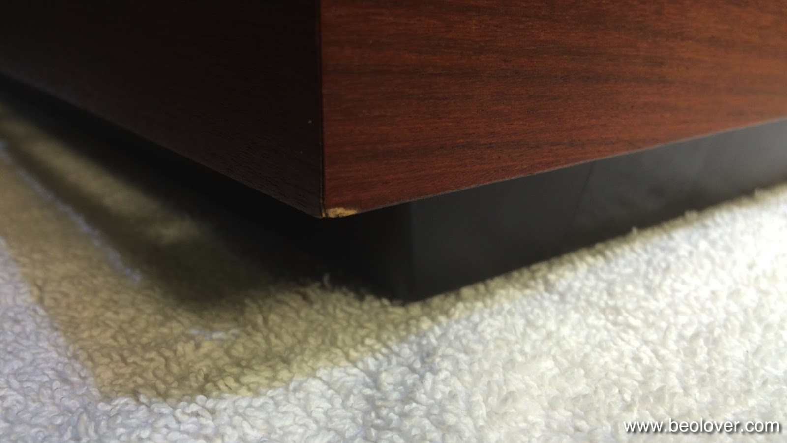
So far so good. After I took it out of the box I found that it was quite pristine but unfortunately with one flaw:

The other corner is much better:

control and glass panels are very nice:


The key pad is also in very good condition:

And so is the back:

The Terminal should also be quite lovely once cleaned up:

So all in all, a pretty good starting point for a restoration!
Beogram 4002 (5513): Replacing the Electrolytic Capacitors
Today was recap day for the Beogram 4002 (5513) that I am currently restoring. I used my recently developed 3D adapter to replace the combined 4700/1000uF capacitor with modern, smaller 105C grade cans. Here are a few impressions.This is the original setup:

This is the 3D printed adapter with the new capacitors:

And a detail picture of the connections during the installation process:

And mounted in place. The 3D printed adapter fits into the original capacitor mounting clamp:

After the reservoir caps I also recapped the main board. This shows the original condition:

And after replacing all the Ta and Al electrolytic capacitors:

The sole capacitor on the output relay board will be exchanged once I take the keypad out to install a rebuilt replacement supplied by an expert beofriend in Denmark.
Monday, September 21, 2015
Beogram 4002: Replacing the RPM Indicator Bulbs with SMD LEDs
I continued working my way through replacing the lightbulbs in the Beogram 4002 (5513) that I am restoring right now. Today was RPM indicator day. I took this as an opportunity to further improve my LED replacement approach. In an earlier post I described how to replace the incandescent bulbs with the red and green LEDs of a RGB through hole 5 mm LED. This worked fairly well, but I was not 100% happy with the homogeneity of the back illumination of the RPM trimmer scales. The issue with standard through hole LEDs is their directed emission pattern out of the top of the LEDs. This made it necessary to sand their bulbs into a matte surface and also painting the tops black to prevent a too high emission on one side of the trimmer scales.
My latest approach is based on my current approach to implanting LEDs for the position scale illumination of Beogram 4000s. I changed the PCB shape to fit behind the bulb covers of the 4002 bulb housings, and I adapted the current limiting resistors (10k for green and 2.5k for red) to the 21V operating voltage and the different illumination angle of the diffusing cavity. I made a short video about this updated approach:
Sunday, September 20, 2015
Beogram 4002: Replacing the Detector Arm Light Bulb, Discussion of the Circuit and Relevant Oscilloscope Traces
The Beogram 4002 that just arrived needed a new light bulb for the detector arm. I replaced it with a new one. While it is a fairly simple operation to exchange the bulb, it can be a bit tricky to get the deck working again if the new bulb is not in the correct location. I made a short video about the progress that shows how to implant the new bulb, and also discusses the adjustment of its position. The video also discusses the relevant parts of the circuit and shows key oscilloscope measurements on a working detector set-up:
Here are high res pics of the oscilloscope traces. This shows the weak signal at the base of TR3 while the platter spins under the detector:

This shows the signal after amplification through TR3 at its collector:

The signal is now about 6Vp-p. I have seen values between 5 and 7V in different 4002/4 units. This shows a representative trace at this point for a light bulb that is not properly adjusted, i.e. does not put enough light under the sensor lens:

Note that the Vp-p is now less than 1.5V due to the reduced light intensity. This shows the resulting signal at the base of TR4 after it passes capacitor C16:

the signal is now 1Vp-p but at a 21V offset to pull TR4 down and turn it on. When it is turned on capacitor 18 charges up with a sawtooth in sync with the platter ribs as they pass by under the detector:

Finally, the charged capacitor pulls the base of TR6 up via R34 (1M) and with this the tone arm lowering circuit is deprived of voltage and the arm cannot be lowered anymore. What a lovely analog control system!
Saturday, September 19, 2015
Beogram 4000: Polishing the Hood
Today I polished the hood of the Beogram 4000 that is on my bench right now (or rather sits next to my Beomaster 6000 4-Channel looking real pretty, even without the hood, playing Miles Davis' The Man with the Horn...;-). Not that I really enjoy the polishing of acrylic hoods, but the effort is definitely worthwhile...these decks just look so much better when the hood is nice and shiny. Usually they come in with significantly scratched hoods. This one was not different. Some deep ones - when one can feel them with a fingernail, one needs to start with 200 grit sand paper to even things out before starting to polish it back to new-like sheen. This one definitely was a candidate for the 200 grade:


And smaller scratches all over the surface.

This shows the hood after the 200 and then 400 grit:

And then during the Micromesh polishing steps:


This shows the end result after polishing with Micro-Gloss:

Pretty! Absolutely worth the multi-hour effort! There is no true Beolove without some degree of pain...;-)
Beogram 4002 (5513): A New Arrival on Beolover's Bench - A First Impression
A Beogram 4002 (5513) arrived yesterday in need of some TLC. Today I had a first look. Overall, this deck gave me a pretty good impression. It is fairly clean and has only little cosmetic damage. My customer did a good job with regard to packaging. It was double boxed and the sub platter was held in place with a piece of HD foam - very nice! Unfortunately, the tone arm transport support clamp came off (red piece in back). But the arms were also supported by foam, so it seems nothing got damaged and we were lucky to that end.

The orange fragments on the panel below indicate that the rigors of transport led to a disintegration of the transport lock bushings. This is common in the 5513 models. The older 4002 and 4000 models seem to have bushings made from a different (gray) material, which were able to withstand the aging process better. I recently developed a 3D printed replacement part that can easily be installed. It is available at the Beolover Shapeways Store. This deck will definitely see them in place before I ship it back.
Then I took out the aluminum panels and it seems all original under the hood:

I will do a recap and replace all bulbs with LEDs (except the sensor arm bulb - still do not like my LED replacement that I developed a while ago - it is too bright - something to look into in the future).
Also the keypad has the usual smudges on the more often used keys. This will be fixed by a restored replacement unit. The other major cosmetic issue of this unit is the scratched hood. The good news here is that the hinge, the plexiglass, and the aluminum trim are in good condition, i.e. polishing is all that needs to be done to get this back to a new-like look. Then there is some minor damage at the right front corner of the rosewood plinth. I expect that this can be made almost invisible by a bit of touchup.
So all in all, a pretty good starting point for a full restoration that will bring this deck back to its original glory.
Friday, September 18, 2015
Beogram 4000: Adjusting the Platter, Cleaning the Panels and Installing a 3D Printed Guiding Washer for the Cabinet
Today, I spent some time detailing the appearance of the Beogram 4000 that is on my bench right now. First I adjusted the platter height and position within the main aluminum panel. This is an important task, since only if the platter is centered and flush with the panels the Beogram looks right. When I got it the platter was way too low (and also so out of center that it was scraping on the panel):

So I adjusted the main bearing and the three suspensions of the chassis until things were right. Visit the original post for two videos that show in detail how to do that properly.
Here is a picture with everything adjusted and cleaned (the panels usually clean up very nicely with Mr. Clean Magic Eraser pads - just wet them a bit and then clean along the brush direction of the panels...):

How lovely! I can't wait until I'll have the hood restored!
While I played with these adjustments, I also rid this Beogram of the front center mounting screw of the plinth. This is a poor design, which they rectified in the later 4002 and 4004 models by installing an eccentric guiding washer instead of the floppy plastic washer and the shoulder bolt.
Here is an impression of the original setup:

I recently designed a 3D printed replacement of the 4002-style washers, which is now available via the Beolover Shapeways Store. There is also a video about installing them. Here is a picture of the new washer in place:

I usually put a dab of Ballistol on the washers before installing them. That makes the plinth move in smoothly.
Thursday, September 17, 2015
MMC20 Cartridge Mount Replacement: Second Design Iteration
This is a follow-up to my initial post about the design of a MMC20 cartridge mount replacement. In the meantime, I acquired a Beogram 4000 with a broken off mount, so now this is 'personal'...;-). Ouch!:

I just received the redesigned Version 2 prints from Shapeways. The main issue with the initial version was that the back part would not fit on the lower part of the original mount that will be reused, and that the contact tab would make intermittent contact. I realized that the issue was the 'bump' that I designed into the tab to press the contacts into the cartridge contacts. One I looked at the broken off tab of my Beogram 4000, I saw that a simple straight shape should work. So version two of my design aspires to closely resemble the 4000 version of it.
Here are a few impressions. Along with the changed shape, I also needed to redesign the tool bodies that are used for pressing the circuit board into the mount while the glue dries:

Hers is a picture of the curing process:

And here the result in comparison with the original mount (this one is from a later Beogram and was supplied by Sonavor (Beoworld)):

Then I tested it on a MMC20S cartridge. It made good Ohmic contact and I measured the usual 770 Ohms per coil:

This iteration now fits very well on the lower (original) part of the assembly:

Consequently, the part also fits into the arm tube:

However, the mounting angle is a bit too steep. From the gap, using a protractor, I deduced that I need to reduce the angle by about 4 degrees. Oh well, back to Autodesk Inventor for Version 3. While I will be waiting for the Version 3 prints I also need to figure out how to plate the PCB traces with gold to ensure long term stability. We do not want to have oxide layers getting in-between our precious vinyls and our ears...;-)
Designing a new part: Quite a laborious process - A resuscitated Beogram 4000: Priceless! This is Beolove!
Wednesday, September 16, 2015
Beogram 4000: Installation of Hood Mounting Screw Springs
On the way to the perfect Beogram 4000 I realized that all 4000s that I so far encountered did not have the hood mounting screw springs that the later Beogram 4002 and 4004 have. These springs conveniently push up the screws making it really easy to take off and replace the hood of these turntables. I checked the service manuals, and indeed the Beogram 4000s do not have these springs included. I guess B&O practiced kaizen here and gradually improved their designs (even though I disagree with the change to DC motors and the implementation of the retro analog control system on the 4002/4 models - the 4000 is much more advanced in this department - I'd love to meet this designer for a chat if he is still around). Anyway, a Pilot G-2 07 pen donated a spring to the Beogram 4000 that I am currently restoring, which I cut in half and installed on the two bolts. I made a short video about the process. Enjoy:
On to doing the final adjustments of the platter height, and then there is the polishing of the scratched hood...this means a nice workout is coming up in Beolover's garage!
Monday, September 14, 2015
Beogram 4000: Zero Force Balancing and Tracking Force Calibration
The Beogram 4000 that I am restoring right now is getting ready for its first real test drive. Time to adjust the zero force balance and the setting of the correct tracking force. I made a video about this procedure a while ago on the occasion of a 4002 that crossed my bench. It is located here on my YouTube channel. The entire Beogram 4000 playlist can be accessed here.
Here are a couple impressions from this particular Beogram 4000 restoration. The first step is zero force balancing. This requires the balancing of the arm with cartridge installed to a horizontal floating level when the force wheel is set to zero. I usually replace the locking washer of the original set-up with a M3 nut since the locking washer has too much play, which almost guarantees a change of the adjustment during the rigors of shipping. The nut holds the counterweight solidly in place:

Once the arm is balanced, the actual tracking force calibration can be undertaken. I do this with the original B&O tracking force balance. The force wheel is to be adjusted that the balance is horizontal after lowering the tip into the desired force spot on the balance:
Time to give this baby a spin!
Sunday, September 13, 2015
Beogram 4000: Installation of a Neutrik Gold Plated DIN5 Plug
Another standard upgrade that I do for Beogram 4000s is installing a new gold plated DIN5 plug. The original ones are not gold plated and tend to be a bit rusty after all these years. This Beogram 4000 was not different:

This shows it taken apart in contrast with the new shiny Neutrik plug (Newark 27B4483) insert:

After cutting the old plug off, I prepared the cable for the new plug. This is a good length for taking the outer insulation off:


It is a good idea to strengthen the signal leads a bit with solder after taking the insulation off. This makes it much easier to solder them nicely into the tabs of the pins. then it was time to solder the plug on:

And here the lovely sheen of new gold contacts:

This is golden beolove!
Subscribe to:
Posts (Atom)