Featured Post

Beogram Commander Remote Control: Maybe This is the Final Version!..;-)

This is a follow up to my recent post about the redesigned Beogram Commander remote control board, which now works in both (DC-motor) Beogr...

Thursday, November 29, 2018

Beogram 4004: DC Motor Restoration

I recently received two Beogram 4004 DC motors for restoration. This is the report on the first one. This shows the motor as received:
I disassembled the motor to get the bearings out for oil infusion. These motors use Oilite porous brass bearings infused with oil. After decades of service these bearings run dry (oil gets slowly extracted on the shaft as the motor spins). Luckily, they can be replenished by immersing the bearings into motor oil under vacuum. This shows the disassembled motor:
The bearings are the two small rings on the black pad. I put them in the oil and pulled a vacuum:
Immediately, bubbling started. This indicated that air is drawn from the pores in the brass material, making room for oil to diffuse into the bearing.

After about 24 hrs the bearing stopped and I extracted them from the oil:
I reassembled the motor and installed it into one of my Beogram 4002s. I ran it for 24 hrs, while logging the RPM in 10s intervals with my BeoloverRPM device (available to other enthusiasts - just send an email/message using the contact form). This is the RPM stability curve I measured:
This is as good as it gets...this motor is ready to spin some records again!


Wednesday, November 28, 2018

Canada Beomaster 8000: Checking out the reworked boards

In the last post on the Canada Beomaster 8000 I left off having completed the restored display board.  With that last board completed I can finally begin testing what this Beomaster can do.

Since it has been a week since I last checked this Beomaster restoration I decided to recheck all of the power supply voltages, the no-load current checks and the DC offset checks.


Naturally I tested the display board now that it is reinstalled.


Everything looks like it is working correctly so I test played an iPod Nano into the Beomaster Tape 2 source input. As usual I connected my Beovox S-55 speakers I keep in the lab.

The Beomaster sounds like a Beomaster 8000.

I wrapped up the day by preparing the Beomaster for some upcoming performance tests.
Here is my test setup.
I am applying a 1KHz sine wave of 1.0VRMS to the Tape 2 source input of the Beomaster. I will measure and monitor the voltage across the dummy 8Ω speaker loads as well as measure the output with a QuantAsylum QA401 Audio Analyzer.


The test setup is ready and I ran a couple of preliminary tests.


Later this evening I will start running the performance tests.

Monday, November 26, 2018

Beomaster 8000: Exchanging the Opamps in the Signal Path and Test

After updating the uProcessor board in the Beomaster 8000 that I am working on right now, it was decided to also update the opamps while the unit was in service position. We recently noticed that the opamps in the signal path of the Beomaster 8000 can degrade resulting in increased distortions (THD), i.e. it is a good idea to also replace the opamps when the boards are out for restoration. Here we go:

This shows the control panel PCB before the upgrade:
Most of the 8-pin ICs on this board are signal path opamps. This shows the board with new socketed LF535 opamps installed:


On to the preamp/input board. I forgot to take a picture of the original condition of the board. Here are a couple shots of the board after replacing the opamps with socketed LF353 units (except the phono input, which was replaced with a low noise LM833 type):
A detail photo of the phono pre-amp section:
After implanting the boards I characterized the performance of the unit with my QA400 audio analyzer. The bandwidth curve yielded the spec -1 dBV drop between 100 and 20,000Hz, and the total harmonic distortion (THD) values at volume 5.0 (just below clipping) were 0.008% on both channels, which is consistent with other Beomaster 8000s we measured. See here for a detailed discussion of such measurements. So far so good...the unit went on into our living room to see if the performance of this Beomaster 8000 is consistent in day-to-day operation.


Saturday, November 24, 2018

Texas Beomaster 8000: Final asembly

The happy day is finally here. The Beomaster 8000 from Texas is reassembled and into the playing test phase. I have said before that this is the best part.

To finish up I needed to put the push nuts onto the control panel in place of the temporary holding tape.


I also brushed on some rust eliminator on the other push nuts that hold the two control wheel assemblies.

I stole the flat metal spring that was under the center mounting post of the button panel for use with the press bar that opens the tone control panel lid. I used black hot glue under the two Beolover cables and on the blue wires for the optical sensors. The glue is removable but holds well. The purpose here is to prove strain relief on solder joints where the wires attach to the button panel.

To reinstall the filter & tone control panel lid I had to replace the broken lever for the lid damper assembly.


At last the final reassembly steps. I put the Beomaster cables back in place the way they were originally routed...well, close anyways. I have photos from all of my Beomaster 8000 projects as they first arrived and some of the cable routing was different. Some of that is probably from other people previously working on the units.

Here is the filter & tone control panel side.


Here is the microcomputer and display side.


...and here is everything back together and the Beomaster 8000 plugged in. I polished up the metal panels and this Beomaster 8000 is stunning again.


It will spend the next few days in one of my listening rooms just to make sure it is ready to return to its owner.  It is connected to a Beogram 8002, a Beocord 9000 and a couple of Beovox M100.2 speakers. This should be fun.


Friday, November 23, 2018

Texas Beomaster 8000: Testing the new phono DIN jack

The touch up paint is dry so I can test the phono DIN jack repair of this Beomaster 8000 unit.
There is just enough room on this workbench to fit a Beogram 5000 turntable to check out the phono input.

The phono cable DIN plug fit easily into the repaired DIN jack of the Beomaster.


Pressing the PH button on the Beomaster turned the Beogram 5000 on and it started to play. No problems...it plays wonderfully. I have to add that I am glad that Bang & Olufsen retained remote control functionality within their product lines.

Here are a couple of pictures playing the Beogram 5000 with the Beomaster 8000.


I believe it is time to start the final re-assembly of the Beomaster so it can be closed back up.

Thursday, November 22, 2018

Texas Beomaster 8000: Input source panel repair

When I first received this Beomaster 8000 unit from its Texas owner I noticed that the input source panel had a rather crude repair.


Yuck! Actually I understand why this type of repair was done and it actually works. But it is just so unsightly that it makes it wrong.

Fortunately the there is a Beolover 3D printed part fix for this type of problem. Installing the 3D printed parts is quite easy but the preparation to apply them here took quite a bit of work.

The first step is to remove the epoxy glue. I used some heat from a heat gun and various size razor knives to remove the glue. To protect the plastic DIN jack housing I used tin foil.


The heat did most of the work and I got all of the glue removed.
Now to apply the Beolover 3D parts. They fit perfectly into slots already there on the DIN jack housing.  No glue is necessary.


I figured that all of the rough handling by the glue removal procedure might cause some DIN jack wiring to break and that was the case.


The resulting wire repair task wasn't too bad. I just had to be careful in removing old solder connections and rewiring the broken leads.


The wires all look correct again. I checked them against a known, good spare panel that I have.

I will touch up the scratches on the metal panel with some black paint then reinstall the source panel in the Beomaster.


Wednesday, November 21, 2018

Texas Beomaster 8000: Restoration task on the control panel

The Beomaster 8000 from Texas has been playing music beautifully while I have been working the restoration tasks for the Canada Beomaster 8000 unit. However, a couple of issues popped up during the functional testing.

The first problem happened when moving the microcomputer board and display board out of the service position. All of a sudden the Beomaster wouldn't switch on the +15V power supply again. I have gone over the solder joints of the microcomputer board a number of times now and here it goes off again. Quite disappointing.

To confirm the problem is still with this original microcomputer board I substituted one of my spares again. Just like that the Beomaster was working again. Due to this flaky behaviour I am not ready to trust this microcomputer board in completing this project. I feel like this board needs to be stripped completely down and all of the traces (and vias) reworked from scratch.

For this project I am going to go with one of my spare microcomputer boards. It hasn't failed me yet so it will be perfect for this project.

The second problem happened at the same time and was the volume control wheel ceased to work. The Beomaster volume worked just fine via the remote control so the problem had to be in the control panel. Either the wheel sensors or the cables.

The cables are the most likely suspects as this Beomaster has gone through some rough cable repairs in the past.


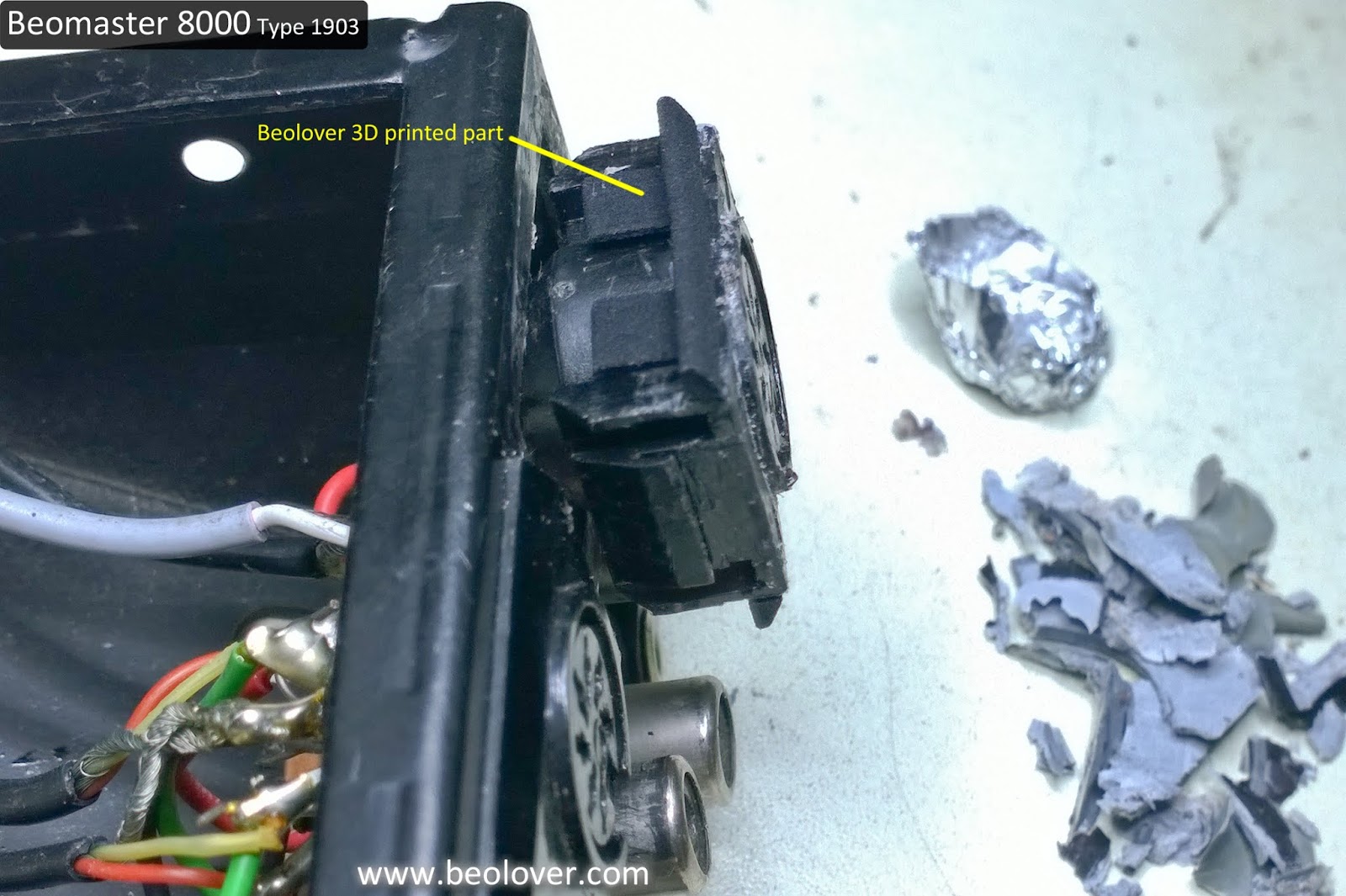
On these Beomaster 8000 control panels the two ribbon cables and the (blue) wires for the rotary wheel sensors can work loose in their small solder joints.

I had to resolder the connections but I decided to go ahead and replace the two ribbon cables with new replacement cables I get from Beolover. That is the best option for success here.

Interestingly, I hadn't noticed this before, the control panel utilizes a flat, metal spring to hold the panel secure in the center. That spring is the same as the flat springs that are used on the Beomaster press bar that opens the Filter & Tone Controls. Perhaps a substitute can be used here and this spring would be free to replace one of the missing press bar springs.


Here is the control panel button board removed and the installation of the new ribbon cables.


Instead of re-assembling the control panel in its final, permanent configuration I will just tape it in place temporarily so I can test that the control panel works and the volume control problem is gone.

Success, both the volume wheel and the FM tuning wheel function properly now.


Tomorrow I will start putting these components back into their permanent positions in the Beomaster cabinet.