Featured Post

Beogram Commander Remote Control: Maybe This is the Final Version!..;-)

This is a follow up to my recent post about the redesigned Beogram Commander remote control board, which now works in both (DC-motor) Beogr...

Friday, September 28, 2018

Texas Beomaster 8000: Preamplifier, Filter & Tone Controls

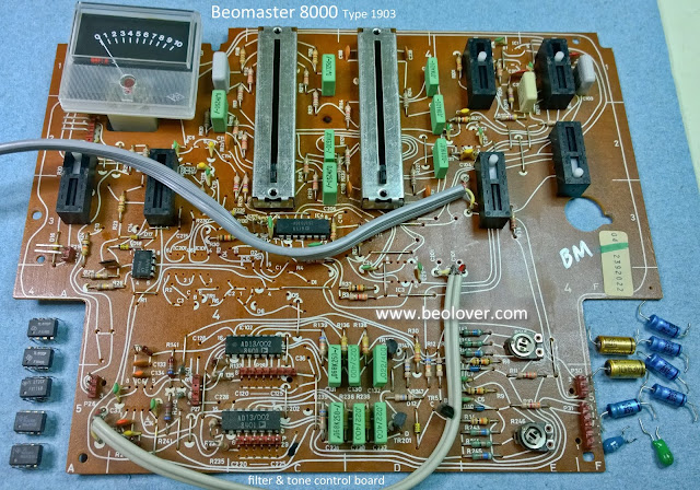
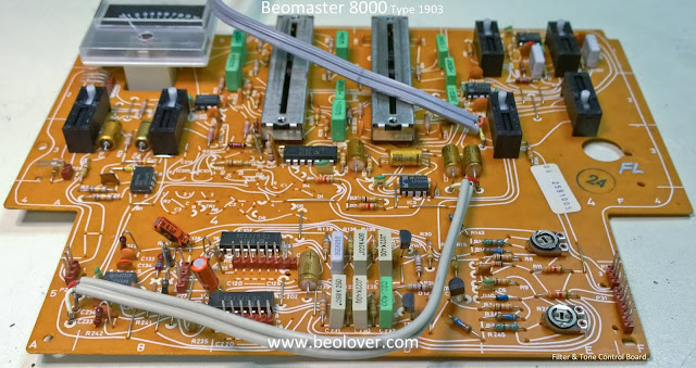
I finished the rework of the preamplifier board along with the filter & tone control board out of the Beomaster 8000 receiver from Texas. The task was pretty much the same as for the Beomaster 8000 from Canada. The electrolytic capacitors were replaced with new capacitors. The LF353N (or TL 072CP) opamps removed and new LF353N opamps inserted. The tone control sliders and source input volume trimmers were flushed out and cleaned with Deoxit. All of the board connector solder joints were reflowed with solder to insure against any weird problems with hairline cracks in solder joints. It is better to be safe than sorry. Especially with audio equipment this heavy.

The two boards look clean and new again. Soon I will be at the point I can give them a try.

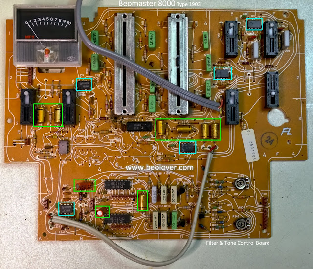
Here is the filter & tone control board before the restoration.


Here are the components I am replacing removed.


There were no real surprises on this board except an area on the trace side that had some suspicious looking solder joints around IC102 and IC202. They just didn't look good to me.


I desoldered the bad looking joints and resoldered them.


After the resoldering I discovered one bad area on the board where most of the trace had broken away.  For that one I wrapped a small wire around the pin that connects to the bad trace pad and soldered everything so it is solid again.


That does it for the filter & tone control board.


Now for the preamplifier board.  Here is how the board came.


This is the preamplifier board after removing components and cleaning. I used Deoxit in the source volume trimmers.


This preamplifier board had TL 072CP instead of LF353N opamps. Both are listed as interchangeable devices in the service manual.

The board cleaned up well and I installed 8-pin sockets for the new LF353N opamps.


Here is the completed preamplifier board.


Thursday, September 27, 2018

Canada Beomaster 8000: Preamplifier Board

The Beomaster 8000 preamplifier board is the next board I restored.  The tasks are similar to the Filter & Tone Control board.  The electrolytic capacitors will be replaced, the LF353N opamps will be updated with new ones.  Board connector solder joints will be reflowed.  The board is cleaned and the input source level trimmers are cleaned.

Here is the preamplifier board prior to restoration.


This is the board where the components to be replaced have been removed. I will clean the board with alcohol and the trimmers cleaned with Deoxit.


This is the board with new capacitors and opamp sockets.


Finally, the completed board.


Wednesday, September 26, 2018

Canada Beomaster 8000: Filter & Tone Control Board

The next component for restoration on the Beomaster 8000 from Canada is the filter & tone control board. The audio signal of the selected audio source goes from the preamplifier board to the filter & tone control board where the bass, treble and filter circuitry lives. This board also has the Beomaster volume control which sets the volume level of the receiver output amplifiers according to control signals from the microcomputer board. The microcomputer board also mutes and restores the volume level when the selected source is changed. Another circuit on the filter & tone control board is for the FM signal strength meter.

Here is the board before the restoration work.


The trace side of the board has screws for securing the filter & tone control plastic panel. This board was missing one mounting screw so I will supply one when I reassemble the board.

Here is the board with the control panel removed. The restoration will involve reflowing the solder connections of the board connectors, replacing the electrolytic capacitors, replacing the LF353N opamps and cleaning the bass/treble slider controls.


Here is the board after cleaning, reflowing, recapping and new LF353N devices.


There is an adjustment procedure in the service manual regarding the left and right channel DC offset for the Beomaster 8000 volume control circuit. If the offset voltage is too high it will result in a static or clicking noise in the speakers when the volume is changing (up or down).  The two trimmers on the filter and tone control board are for adjusting out that offset. There are some associated fixed resistors next to the trimmers that can be disconnected as needed to aid in the offset trimming. The board above has two of those resistors (one in each channel) disconnected. Once the Beomaster restoration is complete I will go through the volume DC offset procedure and readjust the trimmers as necessary. I have found they usually do require some sort of adjusting.

Saturday, September 22, 2018

Texas Beomaster 8000: Big update

Today I got the Texas Beomaster 8000 project caught up to where the Canada Beomaster 8000 project is. Both receivers now have reworked output amplifier board assemblies, reservoir capacitors, speaker switches and power supply boards. Both units also needed cabinet and frame treatments to get back to like new condition. All of those tasks are now reassembled into each Beomaster.

Here is the current state of the Beomaster 8000 from Texas.


The road to this point in the restoration was similar to that of the Beomaster 8000 from Canada.  The bottom plates of the cabinet didn't have any rust but they were quite dirty and had places where bare metal was exposed. So like the previous Beomaster 8000 I took everything apart, cleaned and repainted the base plates.

Here are the base plates repainted.


Next I replaced the reservoir capacitors, changing out the original ones for Beolover replacement reservoir capacitors.

Here is the Beomaster 8000 frame with the reservoir capacitors removed.


Here are the new, Beolover replacement parts next to the original capacitors. You can see that the Beolover 3D printed housing retains the original size which is important in accurately rebuilding the Beomaster 8000.


Here are the new left and right channel reservoir capacitors. I am leaving the wires for the left channel reservoir capacitors disconnected for now so the wires have enough play in them for the left channel output amplifier assembly installation.


While the Beomaster frame still has the base plates removed I will update the two speaker switches. It is easier to work on those with most of the components out of the way.

Here are the two original speaker switches.


Here are the two new speaker switches with the Beolover 3D printed base (so they will fit properly).


Now I can turn the Beomaster frame upside down to reinstall the cleaned and repainted base plates.


It looks quite nice if I do say so myself. There is an extra good feeling you get when everything is new and clean. The Beomaster begins to feel like it is going through the factory as a new creation...even though it is almost forty years old.

Now for the reinstallation of the output amplifier board assemblies. As usual I start with the more difficult left channel.

Turning the Beomaster cabinet back over...


You may have noticed that this time I rotated the output amplifier board 90° the opposite way than I did on the previous Beomaster 8000 left channel output amplifier installation. I am still deciding which way I like best. This time seemed like it was easier but it could just be that I am getting the hang of it. In any case this beats my original method of attaching the heatsink mounted components after installing the amplifier board.

The left channel output amplifier assembly is mounted in place so I can complete the left channel reservoir capacitor wiring now.


Next up is the right channel output amplifier installation. The 90° board rotation technique would work here but I have been able to reinstall the board without turning it.


The final step of this install is to secure the back panel to the heat sinks.


The last task in the restoration catch up is to clean and recap the power supply board. That includes the small heat sink with the voltage regulators.


This power supply board was pretty dirty. It has also been worked on before. The C51 1uF capacitor had been replaced by a 2.2uF capacitor for some reason. I will put everything back to the values that are supposed to be there.

Here is the board with the parts I will replace removed.


Here is the board after an alcohol bath.


When I examined the trace side I found a couple of areas that needed addressing. The solder joints in the middle of the board did not look good. They weren't smooth.


I don't know what was going on there so I de-soldered the ones that looked bad, cleaned up the area and resoldered it.


I also found a trace that was almost broken through.


I scraped away more of the coating to get to the copper trace and used a small piece of magnet wire for the repair.


After the cleaning and solder repair I installed the new capacitors. On the three large capacitors I added a bead of black hot glue to help secure the axial capacitors.  This type of glue works good in this application and can be removed in the future the next time this board requires rebuilding ... 2058? ...I don't think I will still be around :-) .


Here is the completed power supply assembly.  I replaced the thermal insulators on the voltage regulators with Sil-Pads.


I will leave the shield box top and bottom pieces off for now until I can test that the remote control capabilities work.


There is the power supply assembly back in the Beomaster cabinet. This is a major milestone in the restoration of these two Beomaster 8000 units. The next task is to recap the Preamplifier board and the Filter & Tone Control board.