Featured Post

Beogram Commander Remote Control: Maybe This is the Final Version!..;-)

This is a follow up to my recent post about the redesigned Beogram Commander remote control board, which now works in both (DC-motor) Beogr...

Thursday, December 30, 2021

Beogram 4004 (5526): Partial Restoration and Installation of Beolover Commander Remote Control Module

After I repaired the hood of the Beogram 4004 (5526) from Florida, its owner decided to let me do a partial restoration. The unit had shown some platter RPM inconsistencies in the past, indicating that the DC platter motor bearings started to run dry of their oil reserves. This shows the unit with the aluminum panels and platter taken off:

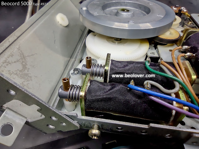
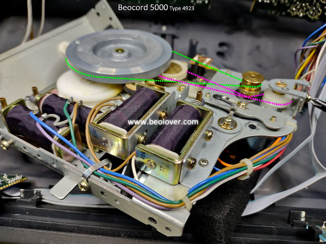
As usual, the first step was to extract the DC platter motor
and disassemble it to get the bearings out for oil infusion:
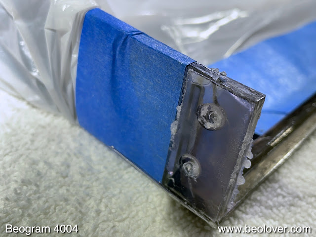
The bearings are the two small donuts on the black pad upfront. I immersed them in motor oil and pulled a vacuum. Immediately, strong bubbling started:
These bubbles are the air drawn from the porous Oilite bearing material. This makes room for oil to inter diffuse into the bearing. This process usually takes 2-3 days, and so I put the motor aside and focused on the other restoration tasks.

Like most Beogram 4004s, this unit also had degraded transport lock bushings:
While one can ignore their degradation as long as the deck is not moved, the fragments can cause the floating chassis to get stuck if they make it underneath during the rigors of transport. So it is essential to remove all the little bits and pieces when the bushings are finally replaced:
For this it is best to remove the 'guts' of the unit and then put a vacuum cleaner to it:
After removal of all the debris and dust it was time to install the 3D printed replacements. They come in sets of two, where each bushing is replaced with interlocking top and bottom parts for easy installation:
This shows the bottom part in place
and the top part added:
Then the lock mechanism can be reassembled:
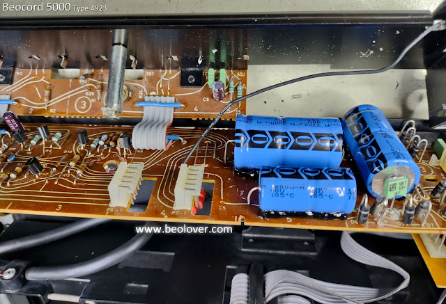
After the transport locks were done I replaced the reservoir capacitor of the unit. These big 'cans' often start leaking and then they lose their capacitance causing operational issues due to an unstable power rail. This shows the original capacitor:
And the modern replacement:
Since the unit has a keypad that is still in pretty good condition, my customer decided to get the Beolover Commander remote control module installed:
The Commander allows controlling the deck entirely without touching the precious keypad via a paired Apple remote control. Which is a great idea since the coating that is on the keypads degrades over time due to the acids and fats from the skin when touching the pads. Read more about the Commander here.

The next step was to replace the cracked plastic pulley of the carriage spindle with a precision machined aluminum replica (send me an email if you need one, too. I'll be happy to get you in touch with the B&O aficionado who took it upon himself to create these beauties)
Then it was time for all the adjustments. First I aligned the arms with the platter and then the platter with the aluminum panels that surround it. Once that was all up to spec, it was time to calibrate the tracking weight. I usually install a M3 nut on the screw that is used to adjust the counter weight. This makes the calibration much more stable over time and it can easily survive transport that way. This shows the original circlip that holds the screw in place:
And here after replacing it with a square M3 nut and a washer:
I use a digital gauge to calibrate the spring based tracking force mechanism scale to be accurate around the usually used 1.2g for B&O cartridges:
Another important adjustment is the arm lowering limit:
Basically the needle needs to be able to go beyond the record surface when the arm is lowered, but not far enough to hit the black ribs on the platter. This is a safeguard against electronics malfunctions that may cause the arm to be lowered without a record on the platter (when everything is in order, the Beogram recognizes the absence of a record and the arm lowering mechanism is disabled).

Then it was time to adjust the tracking feedback sensitivity to make sure the arms remain about parallel when a record is tracked:
After I was done with the above tasks, I had a look at the bearings and the bubbling had stopped. This indicates that the infusion process is complete. So I broke the vacuum and extracted the bearings:
I reassembled the motor and installed it for a 24 hrs RPM stability test with the BeoloverRPM device. The BeoloverRPM allows logging the RPM in 10s intervals over extended periods of time. Perfect for the detection of intermittent RPM issues. Another great function of this little device is that one can adjust the RPM precisely:
This is the curve that I measured:

This is pretty good as far as Beogram DC platter motors go. The slight choppiness of the curve is observed with some of these motors after restoration. It usually goes away after playing the deck for a while as the bearing surface is polished by the rotating shaft due to the torque exerted by the drive belt. At any rate these small fluctuations are far smaller than what the human ear can detect. So it was time to clean the aluminum panels and put the deck back together for a test drive.
I selected a vintage vinyl that I recently bought, "Softly...but with that feeling" by Herb Ellis. This near-new condition Japanese pressing was of course cleaned ultrasonically with a CleanerVinyl ProXL setup before listening.
Here is a picture of this beautiful Beogram together with this lovely record:

A perfect combination. The deck performed admirably during this test spin. I will now play it a bit more and then, if nothing else comes up, it is time for it to be picked up by its owner!
 

Monday, December 27, 2021

Beocord 5000 Type 4923: Tapehead cleaning and playback testing

Continuing on with this Beocord 5000 Type 4923 I am getting closer and closer to wrapping this project up.

In this post I adjusted some mechanical components and cleaned the tape heads (and rubber wheels).
I also connected the Beocord 5000 up to my WOW & Flutter meter.  

First though, the Beocord 5000 has a dedicated motor and pulley to open and close the cassette deck assembly in the cabinet.  I mentioned before that is because the Beosystem 5000 components were designed to be stacked on top of each other.  B&O engineers designed the Beocord 5000 cassette deck so that access to cassette loading and tape controls could be accessed from the front.  This was implemented with a slide out drawer containing all of those controls.


While I had replaced the drawer pulley belt on this Beocord it was opening and closing sluggishly.
It should just open right up very smoothly and close shut in the same smooth manner.


The pulley motor, belt and pulley were all fine. The sluggish operation was elsewhere.

Checking the cassette drawer assembly I discovered that the source of the problem was in the drawer slide mechanics.  Manually operating the drawer slide I could feel that it wasn't as smooth as it should be.  A little too much friction for the drive motor.

Taking apart the drawer slide mechanism I discovered that it works using four rubber/plastic wheels.


I cleaned the rubber wheels and the metal posts they fit on really well.
Then I coated the metal posts with dry lubricant and reassembled the rail assemblies.
The drawer mechanism works beautifully now.  The motor and pulley mechanism effortlessly open and close the cassette drawer.

I also cleaned the cassette assembly.
The tape heads and metal capstan were cleaned with alcohol.
The rubber wheels were cleaned with CaiKleen rubber treatment.
I applied some Molykote DX white grease to the two roller bearings and tape head slide assembly components.


Here is the Beocord 5000 cassette assembly put back together.


The last bench test I performed was a cassette speed drift test and a WOW & Flutter test.
If this cassette deck had exhibited a lot of problems and had it required installing new cassette assembly replacement parts then more service manual adjustments would be required.

As this unit is in excellent shape I am only running a basic speed drift, WOW and Flutter test.

I don't have any B&O produced test tapes from when the Beocord 5000 was produced but I do have some newly created tape calibration cassettes from Genn Lab.

The tape I am using here is for running a DIN 3.15kHz speed test for a cassette tape speed of 1 7/8 inches per second.


I am currently using a Leader LFM-39A WOW & Flutter Meter.  It includes a Drift meter for checking the cassette speed.

With the LFM-39A meter Drift meter zeroed out I can play the Genn Lab test tape and make any necessary adjustments to the Beocord 5000 cassette drive motor.

This photo shows the cassette motor adjustment trimmer access point.


I selected the DIN Indication on the LFM-39A meter to match the test tape I tested with.
The Beocord 5000 did require a bit of tweaking on the trimmer and I set it as close to zero on the Drift meter as I could.

With the speed adjusted I checked the WOW & Flutter meter for the DIN 3.15kHz test tape.  I selected a range of 0.3 for the meter scale and WOW & Flutter for the test mode (W&F).  The output for the test was the right channel playback signal of the Beocord 5000. 


I can't claim this is equal to the B&O measurement methods used to publish the technical specifications for the Beocord 5000 but my results exceed the rated values.  While I am using a non-B&O test tape and WOW & Flutter meter, both are excellent test tools and I use them for all of the cassette decks I work on.

The Drift meter shows a value very near 0%.  The service manual says the value should be ±1.5%.  So very good there on tape speed.

The WOW & Flutter meter shows about 0.05% (remember that it is set for the 0.3 scale).
The service manual says that value should be less than ±0.13% so this Beocord is well within that range.

All that is left to do on this Beocord unit is to test making some recordings.  I have Metal and Chrome bias type tapes that the service manual calls for - TDK-MA and TDK-SA.
I can generate some test tone signals on the record inputs then see what the playback looks like on the audio analyzer.

Friday, December 24, 2021

Beocord 5000 Type 4923: New power supply capacitors and belts

In the previous post for this Beocord 5000 (Type 4923) I left off ready to install new belts and replace the electrolytic capacitors in the power supply.

Here are those tasks completed now.

These are the original power supply capacitors.


...and here are the new capacitors.


Next are the belts.

First is the tape counter belt


Then the clutch wheel and flywheel belts. 
They require some bracket disassembly to change the belts.


Here is the clutch wheel belt


Here is the flywheel belt


Like its other sibling Beosystem 5000 components the Beocord 5000 required some new cabinet feet.


With the Beocord reassembled I connected it to its Beomaster 5000 for a quick listen.


The Beocord is back working again.  It will require some more functional testing so that will be the topic of the next post.

Tuesday, December 21, 2021

Beogram 4004 (5526): Repair of Cracked Hood Hinges

I recently received a Beogram 4004 from Florida for some TLC. The first order of business was the repair of a cracked plexiglass hood. My customer decided to have it fixed since it is in a pretty decent shape except the cracked area. As usual, the crack was around the area where the hinge gets bolted on:

Luckily this was a fairly clean break, and all the fragments were still present:

After I removed the hinge and the aluminum strip side parts it became evident that the other side of the hood also had the same issue, but the parts were still loosely together:

After removing all traces of the old contact cement that held the aluminum strip to the plexiglass, I glued the parts back together with Weld-On #4 acrylic solvent. It can be used if the parts still fit together very well, which allows capillary forces to suck the solvent into the cracks. Once the solvent is in, simply press the parts a bit together and hold for a few seconds. That is it:
On the other side I just bent the cracked off part a bit to enlarge the gap slightly, and that was enough to let the solvent in to mend the parts back together:
Then it was time to install my hinge patches. They are pressed into place with 3D printed clamps that allow the application of significant force on the patches. This basically 'immerses' them into the plexiglass of the hood, as is evident from the dissolved material that gets squeezed out on the fringes:
After letting everything harden for 24 hrs, I removed the clamps:
I drilled out the mounting holes and restored the flat head recesses with a counter sink. Then I was able to bolt the hinge back in:
The final step was to glue the aluminum strip sides back to the plexiglass with contact adhesive. this shows the left side of the hood:
And the right side. Unfortunately, a small amount of solvent was sucked under the blue tape that I used to protect the hood. This left a minor pattern on the plexiglass next to the aluminum strip. If this hood were polished it could probably be removed.
Finally, I replaced the worn rubber pumpers at the front of the hood. Their material degrades over the years. They can be replaced with a small piece of 2mm Viton O-ring. The first step is to drill out the remnants of the decayed material with a 2mm bit:
Then the O-ring bit can be glued in with super glue gel and trimmed to 1mm length:
Beolovely! This hood will close gain with a nice soft 'thump' when the bumpers hit the plinth.