Featured Post

Beogram Commander Remote Control: Maybe This is the Final Version!..;-)

This is a follow up to my recent post about the redesigned Beogram Commander remote control board, which now works in both (DC-motor) Beogr...

Sunday, March 24, 2019

Beogram 4004 (5526): Restoration of PCBs and Reservoir Capacitor

After the restoration of the arm lowering mechanism of the Beogram 4004 (5526) that I am restoring right now, it was time to look after the PCBs and the reservoir capacitor. This shows the main PCB in its original condition:
and a detail shot of the 'RPM control' section:
I replaced the electrolytic capacitors, the RPM relay and the RPM trimmers. The original electrolytic capacitors often fail at this point in time, and the relay/trimmers are often oxidized, which can cause platter RPM fluctuations. This shows the rebuilt board
and the RPM section:
I did the same to the output/remote control PCB:
This is a detail shot of the output section:
I replaced the capacitors and the relay, and also added a switch that allows connecting the system and signal grounds together if there is a hum issue (often an issue when using RCA adapters without ground breakout):
The final step of this part of the restoration was to replace the reservoir capacitor. This shows the original unit:
And the modern replacement:
On to the RPM LEDs and the platter motor restoration!


Wednesday, March 20, 2019

Beogram 400x: Progress Report on the Repair of Cracked Hood Hinges

One sad way for a Beogram 4000/4002/4004 hood to go is that the plexiglass cracks around the mounting holes where the hinge is bolted to the hood. This area of the plexiglass is especially weak since it has to have holes for the hinge, while it also needs to take the highest stress when the hood is opened and closed. So it is no surprise that cracks develop over time, and finally the hood breaks loose from the hinge. 
I have tried a few different ways to fix such cracks over the years with mixed success. More recently, a promising process emerged from my efforts (see here for the original post, which also shows how to deal with the aluminum strip that covers the cracked part of the hinge).

In recent weeks I received a few inquiries for the patches that I used in the above post, which motivated me to come up with a 'hinge repair kit', which would further simplify this repair.

This post gives a progress report on the development of this kit:

For testing I dug out a hood that was damaged when a careless ebay seller sent me a 4002 in skimpy packaging. This shows one of the hinge areas with a 'nice' crack. I salvaged the aluminum strip prior to this experiment for another Beogram, i.e. if you want to see how to get the side parts off, check out the above initial post)

The first step to any successful patching is the removal of the glue remnants, which are always on the plexiglass after removing the aluminum strip:
This glue is soluble in isopropanol if it is soaked for about 20-30 min. I usually dip a wad of cut to size paper towel into isopropanol and then clamp it to the area with the glue:
If the aluminum trim is present on the hood one needs to do it a bit differently (see above post)...anyway, after 30 min the glue came completely off and it was time to try out the hinge kit:
From left to right, there are a clamping block for the inside with the two bolts already installed. Then there is the inside patch, the outside patch and the outside clamping block with the nuts.

The patches are composites of a 3D printed stencil (for precise cutting and hole punching) glued to the foil-coated PETG sheet with double sided adhesive tape. On the picture the stencil is on the bottom, and the top side is the exposed PETG side with a layer of protective foil.

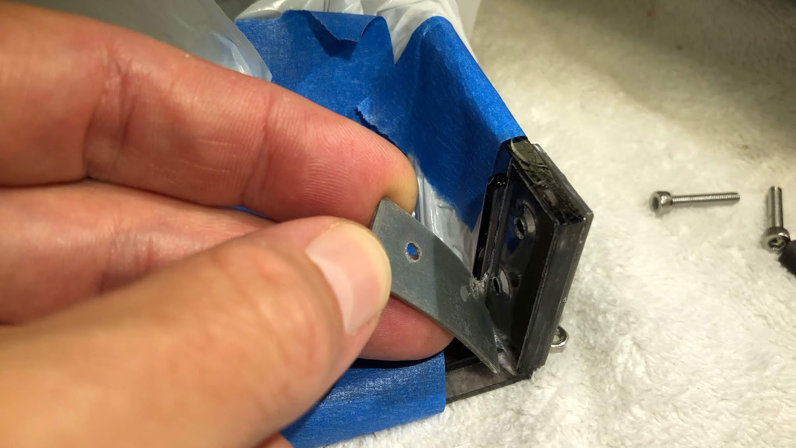
The first step of the installation is to remove this protective foil:
Now the patches can be mounted on the hinge using the two clamping blocks. This shows the inside block and the inside patch:
On the outside, the other patch
and the block are bolted on using the screws and nuts:
At this point the screws should only be hand tight, to leave a small gap to allow the plexiglass glue tp penetrate via capillary forces between the patches and the cracked plexiglass area. Make sure that the outside patch lines up with the plexiglass (the holes in the patch are larger than the bolt, i.e. the bolt does not force it into the proper place like the inner patch)

The next step is to apply some Weld-On#4 glue, which is usually dispensed from a syringe bottle. It is a good idea to squeeze a bit of air out that the bottle has a bit of a vacuum. That makes it much easier to dose the glue between the to be fused parts.
This shows where to apply the glue at the boundary between the patches and the plexiglass:
Apply enough that some of it comes out at the bottom of the patches. It is a great idea to protect the exposed hood areas with a bag or similar. An accidental squirt of the glue can easily ruin the hood (if it happens, do not wipe the glue off. It will only make the damage much worse. Just let it evaporate and accept the fact that the hood needs to be polished now...;-)

After the glue has been applied, the screws need to be tightened well to ensure that the patches bond tightly to the plexiglass:
Weld-On recommends to let the parts harden for 24 hrs or longer for full strength, but after 2-3 hours the mounting blocks can be removed and we can have a look. After unscrewing the bolts the mounting blocks can be removed. The next step is the removal of the 3D printed stencils, which can simply be peeled off from the PETG surface:
and this is the result:
I tried to get the patches off, but it seems they are bonded very well. If you look closely, you can see how some plexiglass got squeezed out at the bottom of the patches, i.e. the glue did make it there. I recommend watching a few YouTube videos about glueing plexiglass sheets etc...it is pretty impressive how the capillary forces do the trick when simply applying a few drops of solvent to the boundary between the materials.
One more note: If the hinge is more deteriorated or if there are small fragments missing, it is better to use Weld-On #16, which has a more viscous consistency. That will be my next experiment with these patches...I am sure, I will soon have a Beogram on the bench with another cracked hood! Stay tuned.


Tuesday, March 19, 2019

Beomaster 8000: Output Amplifier Solo Project

A Bang & Olufsen enthusiast and Beomaster 8000 DIY restorer from Canada sent me one of his Beomaster output amplifier assemblies to sort out. On his recapping and restoration project he was having trouble getting this output amplifier to adjust correctly per the service manual.

There are two of these output amplifier assemblies in a Beomaster 8000. One for each channel.  Only one of the amplifier channels is giving him a problem so he sent the bad actor to me.

Here is the output amplifier assembly as I received it. The heatsink components all look good but the amplifier board has problems with failing component solder pads. They have likely been over-heated and have released from the board. The owner attempted to repair them but I found problems with those.


The electrolytic capacitors have already been replaced as well as the two 100Ω trimmer resistors for the no-load current and DC offset adjustments.

I prefer multi-turn trimmers for this board though so I will replace the installed single turn trimmers. I will also de-solder the components associated with the failed solder pads and make repairs to those. 

Here is a closer look at the trace side of the board with the problems.


The worst section of the damage is the broken solder pad for the positive lead of capacitor 5C211 (100uF, 16V). Examining the traces for that capacitor I see that it can be remounted across two of the solder pads for the 5R200 (DC Offset) trimmer...which I am replacing anyway. 

I installed a smaller, radial type electrolytic capacitor for 5C211 and it fit very nicely.
Here are pictures of the reworked amplifier board.


Capacitors 5C202 and 5C215 each had a broken solder pad so I routed their connection paths using the purple colored wire shown in the picture below.


This board is ready for bench testing where I will make the no-load current adjustment and the DC offset adjustment.

The first step of bench testing is to reset and check that my bench DC power supplies (that will provide the ±55VDC rail voltages) are correctly set to a current limit of 0.15A. That will protect the board (and me).

After the current limits have been set on the power supplies I can connect up the power and ground wires to the output amplifier board for testing.


Next I apply the ±55VDC rail voltages. The output amplifier will not fully be on until I the +15V supply is applied to the amplifier. Here is what the power supplies should look like at this point.


This is a great sign. So far so good. The output amplifier is essentially in standby mode and only drawing 30mA from each rail.

Now I turn the amplifier on by dialing up the +15V supply. I do this a little bit at a time. I don't jump right to +15VDC. Because the no-load current trimmer has been replaced, I don't know where the initial setting needs to be. 
As I start applying voltage to the +15V supply line the current draw on the ±55V supplies starts to go up. I don't want that current to go higher than 100mA to 110mA  (on each supply). Of course I have the current limit on the supplies set to 0.15A as a backup so no real worries. 

In this case I reached 110mA when there was only +6VDC on the +15V supply. The voltage across the two emitter resistors was 24mV.

I turned the no-load trimmer resistor so the current draw on the ±55V supplies dropped back down to around 60mA. Then I increased the +15V supply some more. That iteration continued until I reached +15VDC on the +15V supply and the current draw on the ±55V rail supplies was 100mA to 110mA.
I knew what values to expect here from having bench tested a lot of these amplifiers now. 

The DC voltage across the emitter resistors was now very close to the desired 18mV per the service manual. I adjusted the no-load trimmer at this point to get as close to 18mV across the emitter resistors as I could.


One service manual adjustment down and one to go.
The next adjustment is the DC offset.

For the DC offset adjustment I turned off the bench power supplies and I connected up one of my 8Ω dummy speaker loads. Then I reapplied the ±55VDC rail voltages and the +15V supply voltage.

The output amplifier was on again and I could measure the DC voltage across the 8Ω speaker load.


Initially the DC voltage was a little high, about 0.8mV, so I used the DC offset 100Ω trimmer resistor to dial in around 0.1mVDC of offset. The service manual calls for less that 5mV so this is quite satisfactory.


This output amplifier assembly is ready to rejoin its Beomaster 8000 components and will hopefully be playing music again soon.

Sunday, March 17, 2019

Beogram 4002 DC Motor Restoration

Another Beogram 4002 DC platter motor arrived for restoration. This one came from New Zealand. This shows the motor as received:
I disassembled the motor and extracted the bearings:
The bearings are the two small donuts on the black pad. I immersed them in motor oil and pulled a vacuum:
Immediately air bubbles emerged from the bearings. The vacuum draws the air from the pores of the Oilite bearing material. This enables the diffusion of oil into the bearing. Once all the air has been replaced with oil, the bearing is replenished with lubricant and can be used again. These bearings needed about 48 hrs for the bubbling to stop, after which I extracted them for re-installation:
After assembling the motor I installed it into one of my Beogram 4002s for a 24 hrs RPM stability test with the BeoloverRPM device. The BeoloverRPM allows logging the RPM in 10s intervals over extended periods of time. This is the curve I measured for this motor:

This is as good as it gets for a Beogram DC platter motor, i.e. it is time for this motor to travel back home to New Zealand!


Saturday, March 16, 2019

Beogram 4002 DC Motor Restoration

A DC platter motor from a Beogram 4002 arrived from Australia. It showed the usual RPM instability indicating dry Oilite bearings. This shows the motor as received:
I disassembled the motor to extract the bearings for oil infusion:
The two small 'donuts' on the black pad are the bearings. I immersed them in motor oil and pulled a vacuum:
Immediately vigorous bubbling started. Such bubbling indicates that the vacuum sucks out the air from the pores in the Oilite bearing material. This creates room for oil to diffuse into the bearing. After about 48 hours the bubbling stopped and I extracted the bearings from the oil:
After re-assembling the motor I installed it in one of my Beogram 4002s for a 24 hrs RPM stability test with the BeoloverRPM device:
The BeoloverRPM allows the logging of the RPM in 10s intervals for extended periods of time. This is ideal for spotting sometimes intermittent RPM issues, that are difficult to test by just listening to records. This is the curve I measured during about 24 hrs:
This result is about as good as it gets with the DC motor Beogram, i.e. this motor is ready to return home to Australia!