Featured Post

Beolover SyncDrive: DC Platter Motor Replacement for Beogram 4002 and 4004 (Type 551x and 552x)

Late Beogram 4002 and the 4004 (Types 551x and 552x), which have DC platter motors instead of the earlier synchronous AC motors usually suff...

Friday, March 31, 2023

Beogram 4002 (Type 5504): A New Arrival from Australia with a Very Creative Way to Send the Cartridge Along!

The Australian owner of the Beogram 4000 that I just restored also sent me an AC-motor Beogram 4002 (a Type 5504) for the same treatment. Like the 4000 it came double boxed and so arrived in good shape.

This unit came with a MMC20E cartridge. It was packaged in a very creative way. When I put the unit on my bench, I found this:

I removed the styrofoam 'cover' and this was revealed:
A definite first, but I think actually a pretty decent way to send a cartridge if there is no suitable container at hand. The cartridge's light weight ensures that the tape does not have to hold up to too much force when the box gets bumped around during transport or handling. And so it seems to last and the cartridge stayed put. Very carefully I removed the tape and extracted the cartridge, and put it into a Beolover MMC storage container:
This shows the Beogram as received:
The hood has the usual scratching, but it is not too bad. Under the hood it looks pretty decent, except that the keypad has the usual wear from using it. The clear coat seems to deteriorate over time, presumably from contact with the acids and fats in the skin:
The plinth of the unit is also in pretty decent shape, but it has a few minor scuffs and scratches:

The Beogram 4002 usually has transport lock bushings that are deteriorated, and so does this unit. Telltale signs are the presence of orangeish fragments throughout the enclosure like this one:
This Beogram came with a on/off switch. It seems there was a series of Beograms that came with this feature standard. I saw this before:
After this visual inspection, I looked under the aluminum panels. The unit seems 'original' without significant traces of previous 'human interaction':
I plugged it in and pressed start. It came to life, and the carriage found the set-down position for LPs. The platter motor is also running, all good signs!
It looks like this unit is a good starting point for a full restoration! Stay tuned!


Sunday, March 26, 2023

Beogram 4000: Installation of Newly Designed Beolover RIAA Pre-Amplifier Board

In the past I had a few inquiries for an internal RIAA pre-amplifier board for the Beogram 4000. So when the recent re-design of the Beolover RIAA pre-amplifier for DC motor Beogram 4002 and Beogram 4004 finally came together, I decided to adapt the circuit for the Beogram 4000. 

The owner of the Beogram 4000 that re-visited my bench last week for a little warranty issue decided to let me install the new board in his unit.

This post shows how I installed it. For measurement data, please, check out my post about the characterization of the 4002/4 version, which has the exact same circuit.

This show the board in its current form:

It is still a prototype board and has a couple features that will be removed for the final version. I was not sure how I would power the amplifier in the 4000 since it is set up differently compared to the later 4002/4. I ended up connecting to the 24V rail. The amplifier section of the board is not affected by this, and so this version is already suitable for regular use. 

The 4000 is still fully wired with directly soldered harnesses. This means the board needs to be soldered into place in the 4000. In the 4002/4 the board is simple plug and play due to their more modern design with wire-to-board connectors. Due to the 'permanent' soldered installation I gave this board two switches, with which one can route the output signal through the amplifier, or bypass it in case a traditional Phono amplifier input will be used.

Anyway, let's do the installation! Exciting!:

This shows the output terminal of the Beogram 4000 with the red switch that I installed last year to enable connecting signal and system grounds if there is a hum issue.

Here a detail-photo of the terminal:
The first step was to remove the output cable and the switch from the terminal:
Then I removed the screws that bolt the terminal to the enclosure bottom:
The Beolover RIAA board simply screws on top of the terminal 'bar'. The mounting holes are slots, i.e. the board can be pushed up to the wire terminals for directly soldering it to the contact pads on the board:
The next step is to solder the terminals to the matching board pads:
Then the output cable can be soldered to the output terminals of the RIAA board. They are spaced exactly like the terminal pads, i.e. the output wiring does not need to be modified, and it can directly be soldered in place:
The last step is to connect the red power wire to the 24 rail of the Beogram. A convenient spot is on the main board, where the 24V rail comes in on another red wire.

The strange 6-diode contraption in the back is the Beolover's approach to replacing the Wien oscillator light bulb with a diode based Automatic Gain Control for easy oscillator startup....but that is an entirely different story...;-)

The final step is to pull the output cable a bit further out of the enclosure in the back since the RIAA board pushes the wire terminals a few cm towards the back of the enclosure.

And that is it. This Beogram 4000 can now directly be connected to any modern receiver without Phono input.

Saturday, March 25, 2023

Beogram 4000: Platter Motor Stopped Working

Last year I restored a Beogram 4000 from a customer in the UK. Unfortunately, he recently contact me since the platter motor stopped working. 

After receiving the unit I put it on the bench and started looking into the issue. first I checked the power rails and the reed relays. Everything tested fine. The next step was verifying the motor signal. I measured at the motor capacitor, and there indeed was no signal.

So I did the classic 'follow the signal' approach. I measured the oscillator signal at the collector of TR8, which checked out o.k.: 

The oscillation is not a perfect sine wave, since I had to replace the light bulb in the Wien oscillator with diodes when I restored it last year.  But so far so good...now I measured at the base of TR9, which should essentially show the same signal, just shifted to zero V since it is coupled via C6 to loose the DC component. But the signal was gone:
So it had to vanish somewhere between TR8 and TR9. I measured all the connections between TR8 and TR9, and it turned out that the signal vanished after the motor trimmer VR3. I replaced VR3 with a modern 5k 25 turn trimmer, but no cigar! The signal was still gone after the trimmer. At that point it dawned on me that there must be a short to GND somewhere. A closer inspection of the board yielded this:
R24 and R20 were touching! Something had bent the two resistors together, which effectively connected the base of TR9 to GND. I bent the resistors apart, and voila: The motor signal returned. This is the 33 RPM trace
and here is the 45 RPM.
So the trimmer had been replaced unnecessarily. This shows the new unit peeking through the access hole in the PCB for adjusting the motor voltage:
I put the platter on and a cartridge to see if I could play a record successfully. But the arm did not lower on the record. I realized that the sensor arm was dark, i.e. no power to the LED light source I had installed last year. I measured the voltage at the LED and it turned out that it was 0V. So I looked for interruptions in the connections between the PCB and the LED. And quickly I found the culprit: The yellow wire that connects 6V to the carriage had broken off its terminal on the PCB:
I soldered it back on, and now the deck is playing beautifully again! I will play a few more records, and then it should be time to travel back to the UK.


Friday, March 24, 2023

Beogram 4002 (Type 5513): Restored Keypad and Plinth, a New Hood and Installation of the Beolover Commander Remote Control

A few weeks ago I completed the functional restoration of a Beogram 4002 (Type 5513). This post reports the work that was done. This is how the unit looked like at that point:

While performing like new again, there were two main cosmetic issues: The plinth had a strangely bleached area upfront. Also the keypad had the usual damage from touching the coating with bare fingers. The acids and fats from the skin seem to have adverse effects on the coating material:
My customer decided to let me replace this keypad with a refurbished one. Unfortunately, the plastic inserts that clamp the RPM panel down had cracks. This is a relatively common issue, causing the RPM panel to pop out occasionally. The cracked parts are shown on the right:
On the left are replacement parts that have become recently available at the beoparts-shop. They are exact reproductions of the original shape. All one needs to do is to remove the springs from the original parts and clip them into the replacements. This is shown here:
This shows the new parts installed on the left
and right side of the keypad frame:
This shows the restored keypad and the Beolover Commander Remote Module installed.
This shows the cosmetically restored Beogram. The plinth is the original plinth. The bleached area has completely vanished! Very awesome. This work was done by Vintage Hifi Nut. I am really impressed by his work. This plinth looks like new, like it never happened!
Upfront you can see the Apple Remote that can now control this deck via the small IR receiver that pokes out below the plinth. You can see it in the photo to the left of the remote if you look carefully.
I decided to celebrate this successful cosmetic restoration by playing a recently acquired CTI record from 1974, "Freddie Hubbard / Stanley Turrentine With Ron Carter, Herbie Hancock, Jack DeJohnette, Eric Gale – In Concert Volume One" (CTI 6044). Of course, this record was thoroughly cleaned on a CleanerVinyl ProXL System combined with a UC-3360 multi-frequency ultrasonic cleaner before listening. This restored the sound of this record to its original glory.

The final step of this project was to install the new hood. It also came from the Beoparts-shop in Denmark! These hoods are manufactured via injection moulding, exactly like the original hoods. This means there are no seams like you find them on previously available hoods made by fusing laser cut panels together. These hoods look exactly like the original ones.

This shows the new hood together with a new aluminum trim:
I used my recently developed alignment jigs to get the strip precisely centered. I usually align the strip, then make a small pencil mark across strip and blue tape that I put on to protect the pristine plexiglass while working on it:
The pencil mark allows an easy alignment once the glue has been applied and things need to proceed quickly.
The next step was to remove the hinge from the original scratched hood. In order to get to the screws one needs to lift the sides of the aluminum trim. I usually do that with a razor blade that I carefully insert between trim and hood:
This shows the removed hinge:
Then I bolted the hinge into the new hood and applied the aluminum strip:
Beautiful! This Beogram is ready for duty again and will soon be reunited with its owner!


Thursday, March 23, 2023

Beogram 4002: DC Platter Motor Restoration

I recently received a Beogram 4002 DC platter motor from a customer in New York City. It exhibited the usual RPM instabilities that come from dry bearings.

This shows the motor as received:

I took it apart to get to the bearings. They are the two small donuts on the black pad upfront:
I immersed them in motor oil and pulled a vacuum. Immediately strong bubbling started:
Bubbling indicates that the vacuum draws the air from the empty pores of the Oilite bearing material. This makes room for oil to diffuse into the material. After about 3 days the bubbling stopped. This meant the pores were full with oil again. I extracted the bearings:
I reassembled the motor and installed it in one of my Beograms. Then it was time for a RPM stability test with the BeoloverRPM device:
It allows logging the RPM over extended periods of time. This is the curve I measured after about 24 hrs:
This is a decent curve, but there are still some minor variations (they are much smaller than what one can discern while listening to music). I see this once in a while with restored motors. My hypothesis is that the top bearing and the shaft are at a slightly different position relative to each other after the refurbishment, and so the shaft needs to 'polish' the bearing a bit before the motor will run more stable again. In my experience this may take a few days or even weeks of running time.
At any rate, this motor is ready for duty again and will soon be shipped back to be reunited with its Beogram 4002!


Wednesday, March 15, 2023

Beogram 4000: Complete Functional Restoration

This post describes the work done on a Beogram 4000 that I recently received from Australia. See this post for my initial assessment of the unit.

This photo shows the unit with the aluminum panels and platter removed:

I usually start with rebuilding the carriage:
I removed all of the moving parts of the arm lowering mechanism, and the components of the drive system that moves the carriage:
While these parts are being cleaned, it is the perfect moment for restoring the solenoid activated switches to the left of the yellow solenoid. As usual they were bent out of shape and oxidized:
The only way to rebuild these switches is to remove the terminals. Two of the small boards are soldered to another PCB underneath them. It is best to unsolder these boards while the carriage is 'up' for removal of the switch terminals
The third board can be unscrewed and removed after un-soldering the three wires that are attached to the terminals. This shows the small boards after I removed them:
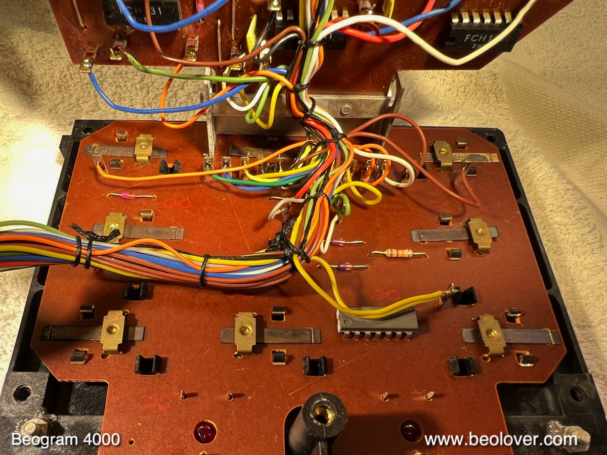
While the carriage is removed, it is also easy to get to the board that detects the carriage position with five switches. This shows it from above with the plastic switch actuators visible:
This shows the board flipped up, which reveals the switch terminals and the solenoid current limiting resistor:
I removed all the terminals from the switches:
While the carriage position board is up it is the best moment for replacing the TIP41 transistor that drives the solenoid:
This transistor often fails, and therefore a prophylactic replacement is a good idea when restoring a Beogram 4000. This shows a modern higher voltage version, a TIP41C implanted:
This shows the cleaned and gold coated switch terminals:
I usually coat them first with nickel and then with a cobalt-gold alloy. This type of coating is best for switches due to its hardness and resulting high mechanical stability. This shows the carriage position switches but back together and a new solenoid resistor installed:
Beo-golden-lovely!..;-). I also cleaned the plastic switch actuators with an ultrasonic cleaner before putting them back onto the board:
This shows the straightened out and coated solenoid switches put back together:
And reinstalled next to the solenoid:
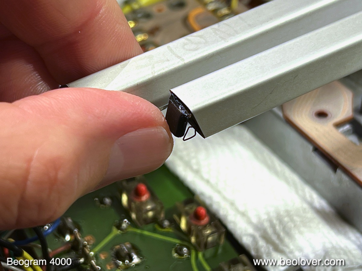
While the carriage is removed it is also a good idea to replace the cartridge mount. The Beogram 4000 was unfortunately fitted with cartridge mounts that were made from a plastic that becomes brittle over the years. It tends to break off easily. In this particular Beogram it already had cracked, but was still attached to the flexible PCB that forms the actual contacts that connect to the cartridge coils:
For replacing the mount the arm needs to be removed and 'cooked' for about 30 min:
Then the assembly can be pushed out (after removing the screw that holds it in place if it is an 'old-style' cartridge mount like in this case) with a suitable rod that fits into the aluminum profile:
This shows the new Beolover cartridge mount part next to the original assembly:
When installing the part it is a good idea to use an old cartridge to push it into the right position that the cartridge fits flush with the aluminum profile:
This shows the installed mount:
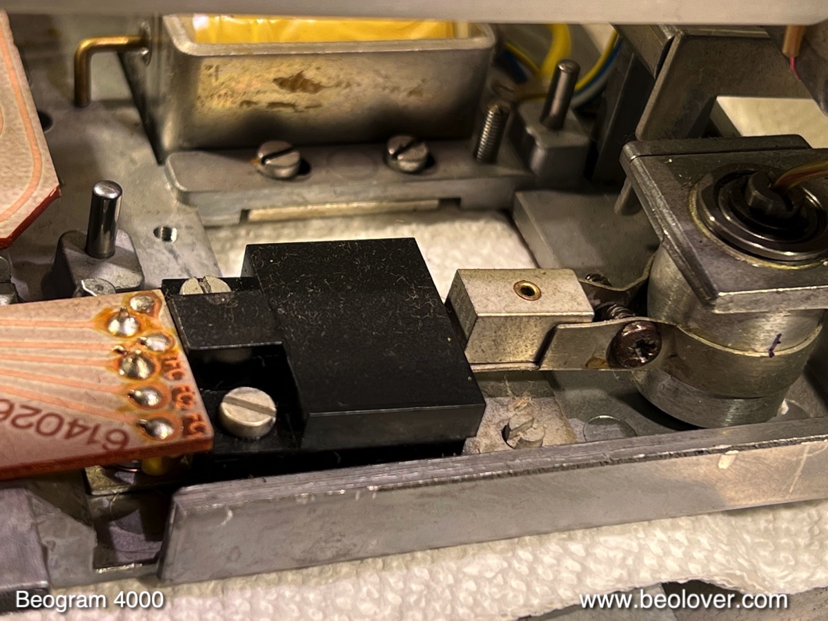
The final item to replace on the carriage was the tracking sensor light bulb, which is located in the black housing under the arms:
I removed it and fitted a Beolover LED based replacement in place.
Then I re-installed the carriage and the mechanical parts, which were cleaned ultrasonically:
I also replaced the rubber gasket in the damper plunger:
It often fails and causes inconsistencies in the arm lowering speed.
This shows the carriage back in place:
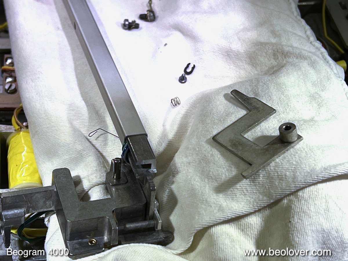
There was one item left to take care on the carriage, but which is best done after it has been installed again: The removal and cleaning of the damper to arm linkage. It can be seen poking out in the back of the arm assembly, fitted into a small "V" cut in the arm that connects it to the tone arm back:
In order to get to it, the sensor arm needs to be removed. This shows the arm removed and the linkage extracted (make sure you do not loose the small spring that is under the circlip that holds the linkage down if you try this at home):
As usual the small copper plate that helps the lateral arm movement while the arm is up was loose:
It is held in place by usually deteriorated double sided tape. I cleaned it and then glued it back in place with a dab of epoxy:
Once the sensor arm assembly is back in place, the arm 'parallelism' needs to be re-adjusted:
Now it was time to rebuild the reservoir and motor capacitor section, and the platter motor itself. This shows the original setup:
I removed everything, cleaned the compartment from some capacitor leakage, and opened up the motor for oil infusion:
I put the motor housing with the embedded shaft bearings into motor oil and pulled a vacuum. This extracts air from the bearings and makes room for oil to interdiffuse:
While the oil infusion happened, I focused on the keypad cluster. This shows it removed from the enclosure and opened up into service position:
As usual, a light tug on the strobe mirror made it come off from the keypad housing. Closer inspection yielded that the diffusor of the 'light box' for the uniform illumination of the carriage position scale had also started coming loose:
The contact terminals of the keypad switches showed the usual oxidation:
I extracted the terminals for electroplating:
This shows them after nickel and gold plating:
I also removed the switch actuators:
They have different, longer 'pistons' defined by the separation between the actual keys and the PCB underneath them. The longer parts of the pistons go into the plastic fixtures, as shown here:
I cleaned the plastic parts with my ultrasonic cleaner. This shows the terminals re-installed: 
The second PCB under the keypad contains the light bulbs for illuminating the scale and the two red adjustment trimmers for 33 and 45 RPM:
I replaced the bulbs with LED fixtures:
Finally, I glued the separated parts. This shows the position scale cover removed from the keypad assembly, allowing me to get to the diffusor:
I completely removed the diffusor. It came off very easily.
I glued it back into place with a small amount of carefully applied epoxy around the 'box':
I did the same for the mirror:
That concluded the work on the keypad assembly. I moved on to restore the main PCB. This shows it filled up to reveal the component side:
While this board is up, it is the perfect moment to replace the complementary TIP31/32 power transistor pair that forms the push-pull stage that drives the platter motor. They are bolted to the chassis for heat dissipation purposes:
I replaced them with stronger TIP41/42C types. These transistors have a history of failing, i.e. I think it is a good idea to step up their current capability. This shows the new types installed:
Then I did the main PCB. I replaced all electrolytic capacitors, all power transistors, the sensor transistor, the RPM adjustment trimmers and the RPM relay with new components:
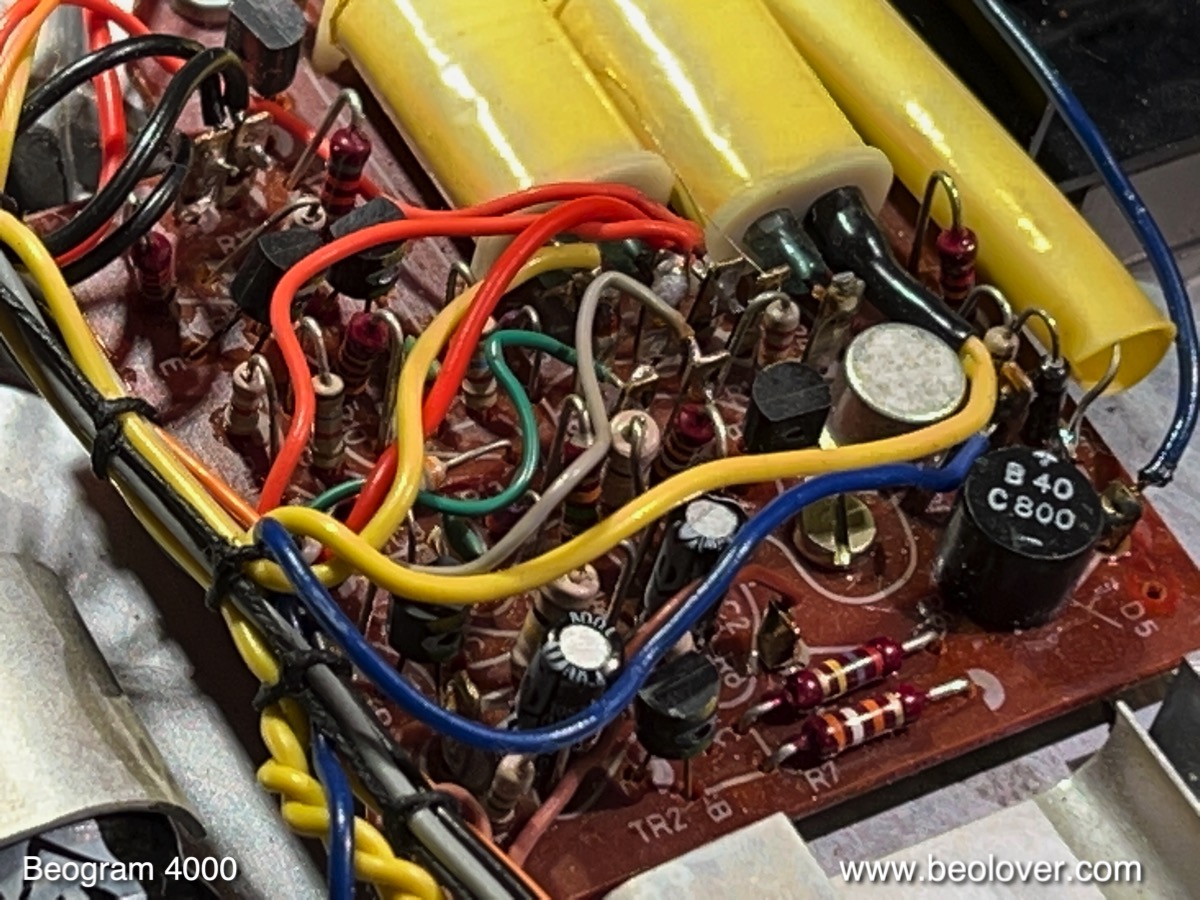
There is a second, smaller PCB in the Beogram 4000, which takes care of the power rails. This board has also two electrolytic capacitors that need to be replaced. They are the two brown units in the lower left quadrant:
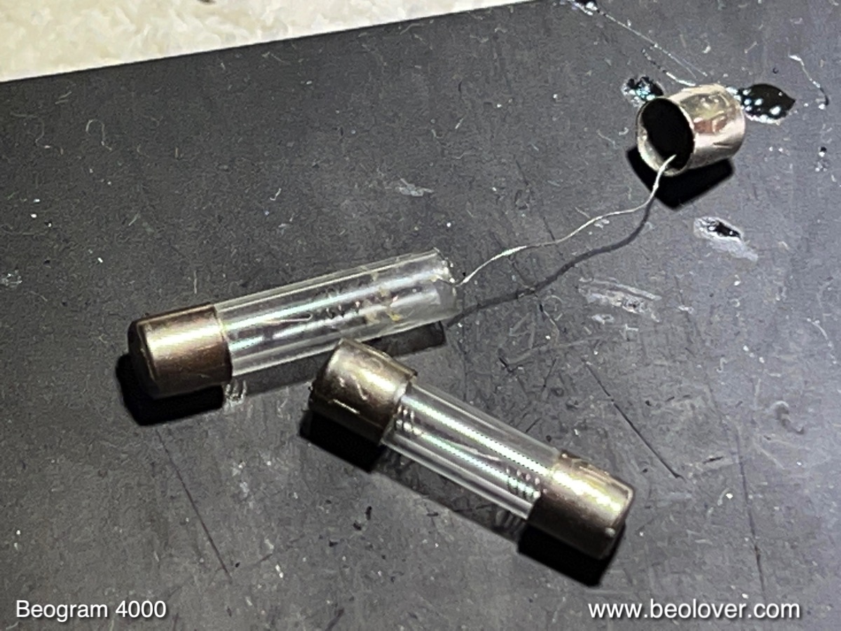
Another item on this board is the 6V rail fuse, which is often deteriorated. It resides in the yellow insulating tube next to the reed relays. This shows it after pulling back the tube:
After a light tug, the fuse immediately separated. I replaced it with a new one:
This shows the rebuilt board:
In the meantime, the oil infusion had come to an end, and I reassembled the motor and installed new capacitors with the aid of a (red) 3D printed fixture that holds them orderly in place:
There was still one incandescent bulb that needed replacement: The one in the sensor arm that provides the light for the detection of records on the platter. This shows the extracted bulb compartment together with the Beolover LED assembly, that directly replaces the bulb: 

This shows the LED assembly implanted together with the original bulb:
This shows the LED in action. It uses a warm white LED, which emits enough red photons to light up the B&O logo in style:
This concluded pretty much the work on the electric system, and it was time to do some measurement and calibrations. First I checked the motor voltage, which needs to look like a perfect sine wave. This shows the 33 RPM signal:
Perfect! On to adjusting the bias of the sensor transistor. I installed a trimmer that allows to calibrate the bias precisely to yield the prescribed 1.8V at the collector of the transistor:
After this adjustment, I measured the sensor response:
The amplitude of the sensor signal was a spectacular 3.8V. Definitely a passing grade! Every dip represents the passing of a platter rib under the sensor.
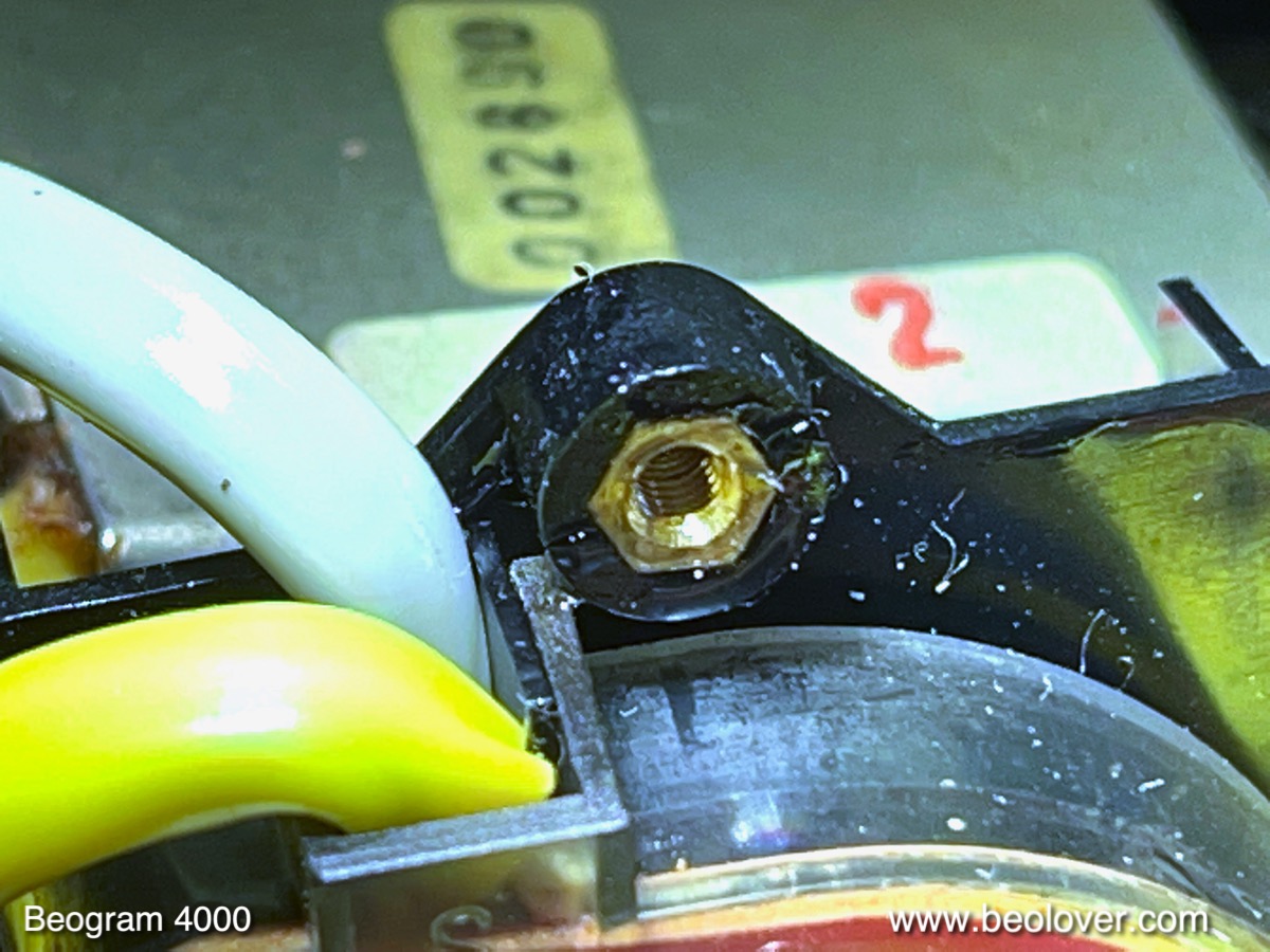
At this point I realized that the threaded insert that allows the cover of the fuses compartment to be bolted down had broken out of its plastic sheath:
I located the broken off fragment and the insert and epoxied everything back on together with the treaded insert in place:
This shows the fuses box with the re-attached insert:
and with the cover bolted back in place:
It is generally a good idea to not over-tighten the screw of the fuse box. It likely broke due to too much torque. 
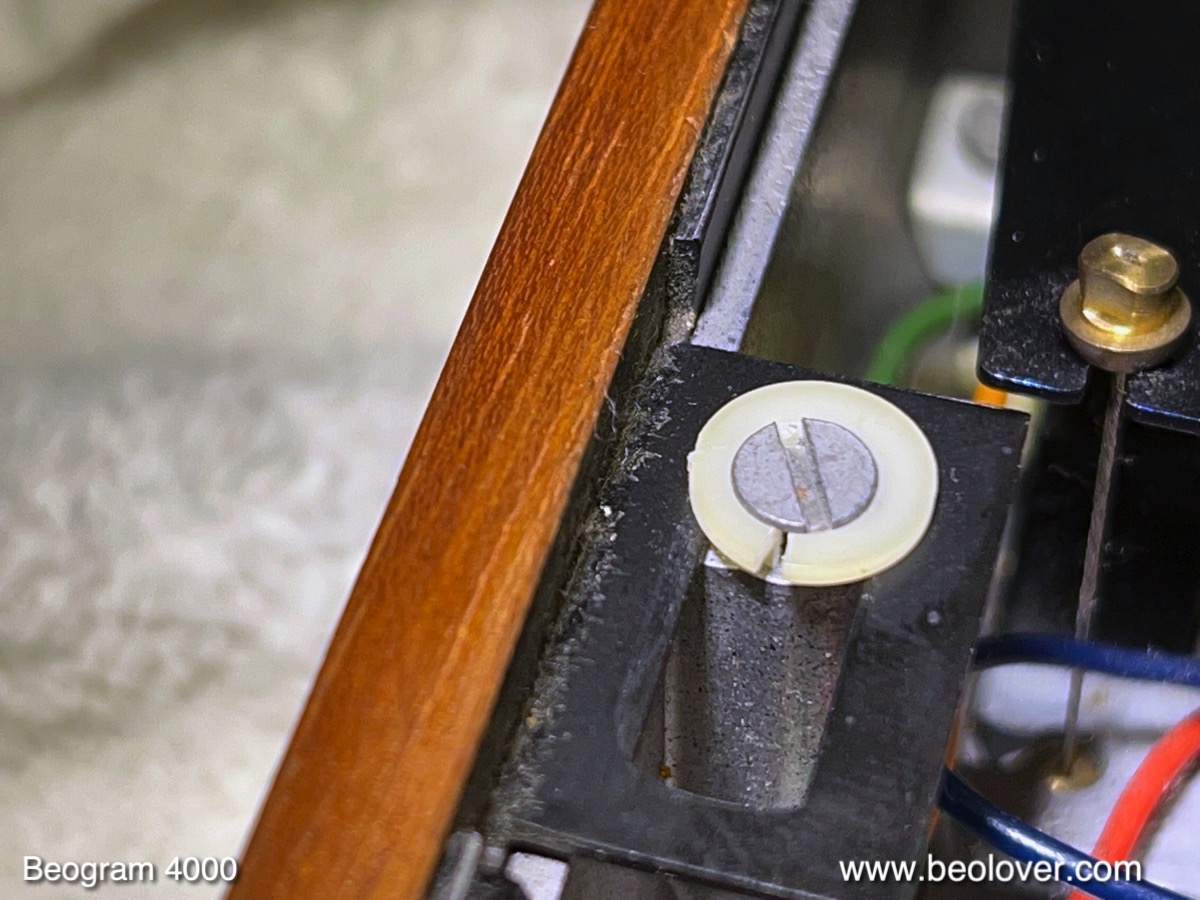
The next step was replacing the cracked plinth guidance washers
with 3D printed replacements:
Then it was finally time to do all the necessary mechanical adjustment. First I aligned arms and platter to be parallel and at the proper distance. Then I adjusted the floating chassis to get the platter level with the surrounding aluminum panels. 
After this process was completed, I adjusted the arm lowering limit to make sure the needle would miss the ribs on the platter should the arm ever be lowered without a record present due to a malfunction of the record detection circuit:
The next step was to calibrate the tracking weight to be accurate around 1.2g, which is the specified weight for most B&O cartridges:
It is usually best to not rely on the weight scale on the adjustment wheel. I always use a digital scale for getting the weight right.
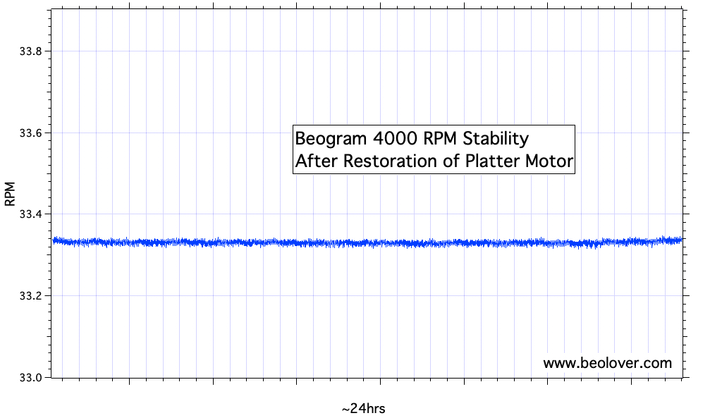
This restoration was coming to a close, and I finally performed a 24 hrs RPM stability test of the platter motor with the BeoloverRPM device, which allows logging the RPM in 10s intervals over extended periods of time:
This is the spectrum I  measured after ~24 hrs:
This spectrum is as good as it gets. The AC platter motors pretty much never have RPM issues due to their brushless design and synchronous operation mode. 
Before taking a first 'victory spin', I still needed to replace the corroded original DIN5 plug:
I replaced it with a quality modern all-metal plug that has gold plated contact terminals:
And now it finally was time to play a first record on this restored Beogram 4000! I selected one of my favorite Quincy Jones records, "You've Got It Bad Girl" from 1973 (A&M Records SP3041). Of course, this record was thoroughly cleaned on a CleanerVinyl ProXL System combined with a UC-3360 multi-frequency ultrasonic cleaner before listening. This restored the sound of this record to its original glory:

A perfect combination! This record probably was played on a few Beograms back when it came out! I will now play this deck for a couple weeks to make sure there are no intermittent issues. Then it will be time to send it back to its owner!