Featured Post

Beogram Commander Remote Control: Maybe This is the Final Version!..;-)

This is a follow up to my recent post about the redesigned Beogram Commander remote control board, which now works in both (DC-motor) Beogr...

Tuesday, June 21, 2016

Beogram 4002 (5513): Final Adjustments and a Test Drive with Freddie Hubbard's "The Love Connection"

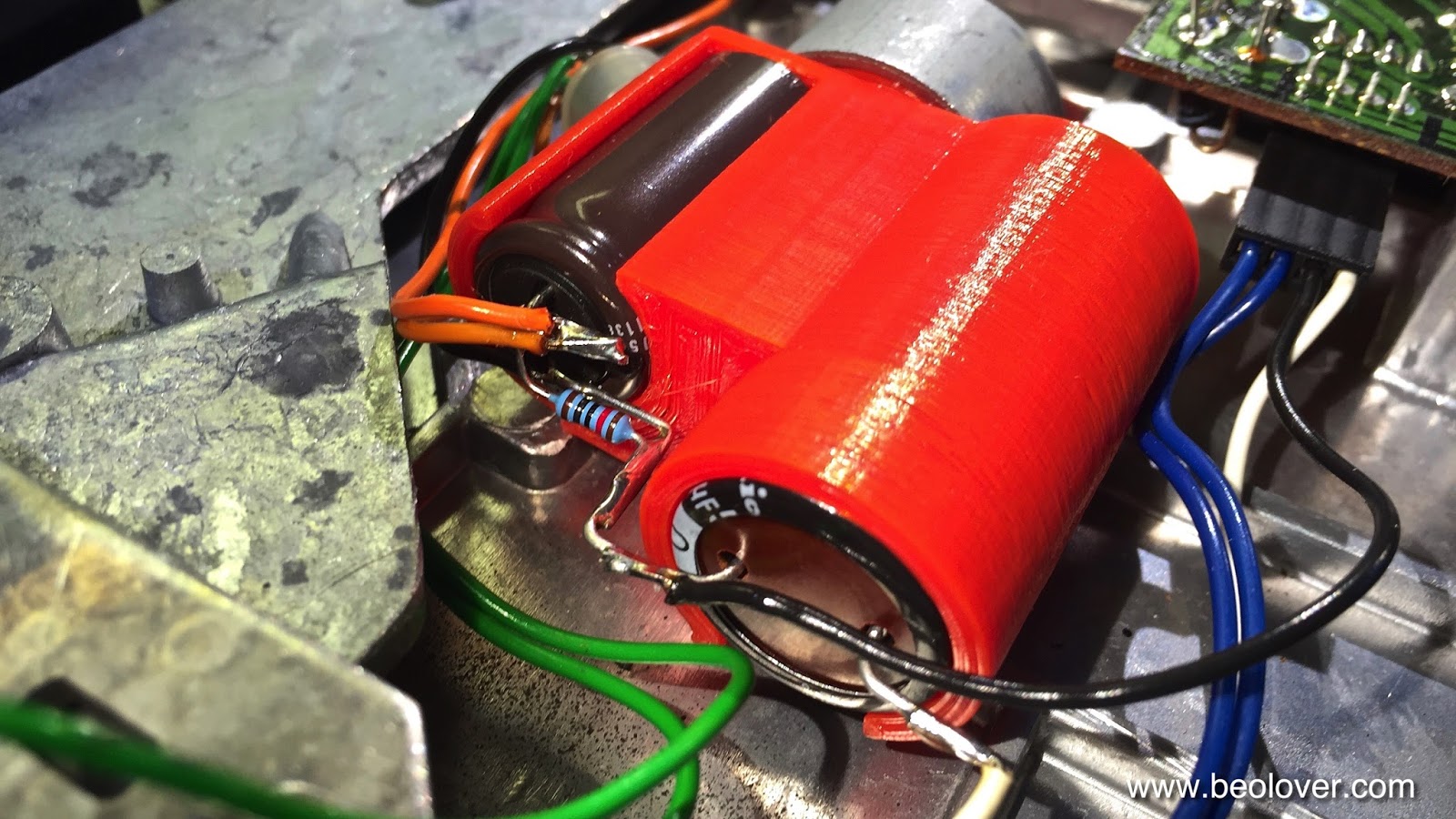
My current Beogram 4002 (5513) restoration has come to an end. I did the final adjustments  I adjusted the platter height and did the sub-chassis alignment. There are two videos on my YouTube channel that show how to adjust the platter bearing and the subchassis (in a Beogram 4000, but the process is very similar in the 4002).

Then I performed the arm lowering limit adjustment. There is another video on my youTube channel that shows how to adjust the lowering limits. This is an important adjustment to make since it can help protecting the cantilever in case of a record detection malfunction. The record detection circuit is not able to detect a light sensor failure by design and therefore if this issue should occur, and the deck is started without a record, the arm would be lowered on the platter (a painful thought!). That is the reason that the 'ribs' on the platter are designed with lowered sections where the arm would lower for the different record sizes.

Here is an impression of the effect of the lowering limit protecting the needle from touching the lower parts of the ribs:
Once the arm lowering limit is set, the tracking force can be calibrated. There is also a video about this process. This shows the tracking force gauge in action during the adjustment:

And then it was finally time for a test of this beautiful Beogram 4002! I selected a recent acquisition to my rapidly growing selection, Freddie Hubbard's "The Love Connection". In my opinion a great record. Unfortunately, it is widely derided for being too 'pop' and having too many pleasing melodies. Surely, it is not real jazz in a traditionalist interpretation of the genre, but it is absolutely great music. I even like Al Jarreau on "Little Sunflower" (I am not usually a fan of his own records). Check it out! Most of the tracks are on YouTube. This is the link to Little Sunflower. Now if they only had come up with a less tacky album cover...;-):
At any rate, this Beogram 4002 looked and sounded great while playing this album via the Soundsmith SMMC20 EN cartridge that came with it from ebay:
Time to send this beauty on to its new owner!


Saturday, June 18, 2016

Beogram 4002 (5513): End Groove Detection Not Working

When I thought I was close to be done with this Beogram 4002 (5513), I set it up to play a first record on it. All went well until the side was through and the needle approached the end groove. The needle went all the way to the record label and then remained there playing an eternal "tk....tk.....tk....". Like in the old days with fully manual turntables...not very beolovely, though!

I removed the platter and had a look. I connected my oscilloscope to the collector of TR17, which translates the optosensor (4IC1) response from the position sensor into a 0-21V 'digital' signal that can be used to tell the control system where the carriage is located. The signal was all good for the major black bars on the position indicator, but was very weak for the run out groove area. This is usually a sign of a poor alignment of the IR diode relative to the light entry slit on 4IC1. The reason that the end groove marks are more critical in this regard is their small width. This creates a situation where a slight misalignment of the diode sends light into 4IC1 from the side, thereby 'muddying' the bright-dark sequence, which lessens the response of TR17. Another reason for end groove detection malfunction is an incorrect distance between position indicator bar and 4IC1. It needs to be pretty close to ensure that the narrow end groove bars really cover the light entry slit.

Anyway, I tried to reposition the IR diode a bit. This shows PCB 4 removed from the enclosure:
The IR diode is right in the center facing the black front of the sensor (this picture is actually from a different Beogram 4002 than the one that was fixed here...I forgot to take a picture before I repaired things).
When I tried to align the diode a bit better, it promptly broke in two:
I guess the old plastic got a bit brittle over the years...what now??

I tried replacing it with modern IR diodes that I had in stock, but to no avail. The circuit that drives the IR diode did not have a low enough impedance to drive the modern high output IR diodes that I had available. Even with 1R88 fully turned the voltage did not reach the prescribed 1.7V across the diode. I elected to not alter the circuit with a smaller resistor, but rather chose to use a classic red 5 mm LED, which had an appropriate low output and power consumption. This worked very well. Here you can see it implanted:
And in action:
Looks pretty, doesn't it? After this repair the end groove was detected nicely. It is interesting to note that the end groove issue probably was there for some time and omitted on the ebay description for this Beogram: It appears the previous owner tried to fix it by adding a thicker line to the end groove markings with a Sharpie pen:
The end groove markers are the narrow lines to the right. The Sharpie line is the wiggly hand drawn thicker line to the left of the narrow lines. The other lines on the left are the singles set-down marker (narrow) and the 45 RPM change marker (wide band).
It is interesting how they used different widths and the end groove lines-array to be able to elicit different and appropriate responses from the control system depending on the carriage position. Ah, the joys of analog control systems. Microcontrollers are so much more effective, but also much more boring...;-). This is Beolove!


Friday, June 17, 2016

Beogram 4002 (5513): Installation of New Gold Plated RCA Plugs

No Beogram 4002 restoration is complete without replacing the original DIN or RCA plugs. The original plugs are usually a bit corroded since they were not gold plated. It is a great idea to install modern all metal plugs with gold plated terminals. This increases protection against EMI interference and also ensured low contact resistance to let those small MMC20 signals travel to your amplifier unimpeded. This gives an impression of the original RCA plugs that were on the Beogram 4002 (5513) that I am restoring right now:
Pretty grim...I cut them off and installed nice Amphenol plugs with a full metal body and plated contacts:
And fully assembled:
Very nice! 

Unfortunately, this Beogram also had its grounding wire shortened:
What is it about cutting off cables?? A significant number of Beograms that found my bench in recent years had severed cables, either the power cord or the output cables. How about just curling them up into a neat coil and leaving them alone if they are too long?? Oh well, I replaced the cable fragment with a new pristine 16 gauge wire matching the RCA cables in length. All good again!


Thursday, June 16, 2016

Beogram 4002 (5513): Oil Infusion of DC Platter Motor Bearings and RPM Test

A rebuild of the platter drive system of a DC motor Beogram 4002 is only complete if the motor bearings are relubricated. Most of the DC motor Beograms experience some form of intermittent RPM variations. The motor bearings are made from oil infused porous brass ("Oilite") and the oil in the pores runs out over time. These bearings can be 'refilled' under vacuum, which draws out the air so the pores can be replenished with oil. The difficulty with this process is mainly to get the bearings out of the motor without damaging other parts. I recently made a video that demonstrates this process in detail.
Here are a few impressions of the process while executed on the motor of the Beogram 4002 (5513) that I am restoring right now:
This is the motor extracted from the enclosure:
And after complete disassembly:
I changed my approach a little in recent restorations when it comes to taking out the bottom bearing. I now unsolder the feedback coils on the side that I lift up to extract the bearing:
I came to this conclusion after accidentally ripping off one too many of the flimsy wires that connect to the coils. they are extremely fragile, and the slightest stress will break them. Hence, it is a good idea to take one of the coils out that one can lift up the board to get the bearing out:
The next step was to infuse the bearings. For this I use a FoodSaver vacuum pump and a mason jar filled with SAE30 motor oil. This shows the bearings after pulling the vacuum. The air bubbles indicate air is leaving the bearing. 
After about 12 hours or so the process stops and the motor can be put back together. Then it was time for a test with my BeoloverRPM device:
The BeoloverRPM allows RPM logging over extended periods of time. Great for spotting intermittent issues. This graph shows the before and after restoration RPM curves over about 24 hrs:
The bottom curve was measured before the restoration and the top curve after. The negative spikes of the original curve show that the motor bearings had issues. After the oil infusion the spikes are gone. Happy listening! This is Beolove!


Tuesday, June 14, 2016

Beogram 4002 (5513): Installation of New 3D Printed Transport Lock Bushings

Before doing the platter and sub-chassis alignment adjustments I needed to replace the degraded transport lock bushings of the Beogram 4002 (5513) that I am restoring right now. It is important to have the bushings in place since the sub-chassis adjustment can only be done properly if they are in place. This Beogram was outfitted with the orange type of bushings,


which all seem to be in various states of degradation at this point in time. The gray looking bushings usually seem to be in much better condition. But these orange ones had to go. I removed the plates that hold the transport locks together, which revealed one of the brittle bushings:
I removed it,
And installed one of my custom designed 3D printed replacement bushings:
Each replacement bushing has two identical parts, so it can be installed by putting in one half from below
and the other half from the top:
Then the threaded rod and the top plate can be installed again:
There is a video about installing new transport lock bushings in my Beogram 4002 playlist. The replacement nylon bushings can be ordered directly from my Shapeways store. This is the link to the part. You would need two per transport lock.


Monday, June 13, 2016

Beogram 4002 (5513): Restoring the Hood

Most Beogram restorations are not complete without restoring the hood. Many are badly scratched at this point in time...So, after plating the keypad contact terminals with gold, I set out to do the hood of the Beogram 4002 (5513) that I am restoring right now. Here are a couple of impressions of the original condition of the hood:
Seems someone went figure skating on it...;-). Another area:
The usual starting point is 220 or 320 grit sand paper depending on the depth of the scratches. This unit had a few pretty deep dings and so I started out with 220. Then it was time to claw my way back to translucency using ever finer paper grit. Here is an impression after the second (320) step:
At that point the hood looks like a piece of dark wood. After going through about 10 polishing steps after about 3 hrs, culminating with the 12000 level of Micro-Mesh, the hood was shiny and translucent again:
As usual the rubber bumpers at the front corners had degraded long ago, and only the part that was embedded in the hood plastic remained:
These bumpers add significantly to the 'user feel' of the Beogram since they transform a plastic-on-wood 'clonk' noise to a solid 'thump' which is much more pleasant. I drilled the decayed remnants out with a 2 mm drill bit that I outfitted with a handle:
Then I implanted sections of 2 mm O-ring using dabs of super glue gel at their ends:
The next step was to trim them to about 1 mm length, which makes the hood sit horizontal (there is a ~1 mm gap at the back when the hood hinge is installed). A 3D printed tool helps the cutting process to be identical on both sides:
Allright! All good now in the 'hood department'! This 4002 is on the way to be a looker again! This is Beolove!


Sunday, June 12, 2016

Beogram 4000: Increasing Tonearm Lowering Delay

After installing the new hood on the Beogram 4000 that I am finishing up I gave it some more playtime together with my Beomaster 6000 4-Channel (they just like each other...;-) and I realized that the arm lowered too fast. I first tried to increase the damper time constant by screwing the vale screw a bit further in, but to no avail. In fact the damper got very slow, but the needle still lowered very fast into the groove. What is going on!

I took the panels off again and had a close look. It turns out that the damper to tonearm linkage is very close to the damper plunger, and so it gets moved immediately when the damper starts moving. Since the damper needs to build up a bit of vacuum inside before it can do its damping action it is faster for the first mm or so and then becomes fully damped. This had the negative effect that the arm would be lowered already during this first mm before the damping action finally set in. 

I always wondered why later 4002/4004 models have a modified damper to arm linkage. This shows the modern version:
The setscrew on the lower end of the linkage allows the change of the distance between damper and linkage when the arm is up. The adjustment instructions in the 4002 manual yield a situation where there is a small gap between damper plunger and linkage, so that the damper does not rush into the linkage during its first mm of movement. This causes the arm to be lowered only after the motion is fully damped.

The Beogram 4000 on the other hand (and some older 4002 versions) have a linkage that cannot be adjusted:
I scratched my head a bit how to introduce that gap a the damper plunger, and after a while it struck me that I could also alter the upper end of the linkage where it controls the lowering of the arm. I added a few layers of shrink tubing to the connecting end which lifted the linkage up a bit, creating the desired mm gap on the other end:
After this modification the arm lowered very smoothly.


Beogram 4000: Installation of a New Plexiglass Hood and Aluminum Trim

My current Beogram 4000 restoration is coming to a close. The final touch of the cosmetic work was to replace the original hood with a newly made reproduction hood provided by Classic Audio in Denmark. Classic Audio also provided a reproduced aluminum trim strip to be applied in the back of the hood. The installation of such a hood is straight forward: Here are a few impressions:

This shows the installation of the original hinge using new stainless M3 screws:

The machined holes in the new hood fit perfectly and the screws went in exactly like they would in an original hood. It is a good idea to protect the pristine plexiglass with a bag or similar while doing this procedure.
After the hinge was mounted, I applied the new aluminum strip. It came with adhesive backing, so all one needs to do is to remove the backing and then carefully apply the strip making sure that it is matching the edge of the plexiglass without making creases or folds. After some initial learning curve I finally had it on:
It is really amazing how clear such a new hood is. This simply cannot be matched by polishing a scratched original one:
Awesomely beautiful! I am very grateful that Classic Audio is providing this great service to the B&O community!
This is Beolove!


Saturday, June 11, 2016

Beogram 4002 (5513): Gold Plating of Keypad Contact Terminals

One of the design peculiarities of the Beogram 400x series are the mechanical switches that are used throughout the control systems of these beauties. The switches are based on spring loaded contact terminals that are either actuated by the user, or in the case of the 4000 by the carriage as it advances during the playback of a record. The trouble-free operation of these Beograms depends on the proper functioning of these switches. I recently started offering electrochemical gold plating of the contact terminals, since in the Beogram 4000 most control issues originate from oxidized terminals in these switches.
The latter 4002 and 4004 models can benefit from gold plating as well since often their keypads have issues resulting in unreliable switching performance. This shows the keypad terminals of the Beogram 4002 that I am restoring right now in their original condition. 

The thick black coating is oxide which needs to be removed before gold plating can be attempted. I unsoldered the terminals and took them out:
This can be a bit tricky, since it should be avoided to bend them. Once they were out I removed the oxide with 2000 grit sand paper and a fiberglass pen and then plated them with gold:
Then I reinstalled them:
Beautiful!


Friday, June 10, 2016

Beogram 4002 (5513): Replacing the Original Dual Main Capacitor

The current restoration of a Beogram 4002 (5513) provided me with an opportunity to further optimize my reservoir capacitor replacement part, which allows the installation of two new 105C grade Japanese capacitors in the space used for the original dual-capacitance can. Such dual capacitors do not seem to be made anymore, i.e. it is necessary to replace them with two individual capacitors. Last year I designed a 3D printed part that holds the two new capacitors, but provides a flange that allows the use of the original capacitor clamp to hold the assembly securely in place.
Here is a picture of the original capacitor. The two contacts on the front are the positive ends of the 4700u and 1000u capacitors integrated into the can:
The negative contact (for both of these capacitors) is on the back side of the can:
I redesigned my 3D part to be more sturdy, but also to be better 3D printable. My 3D design learning curve continues and I am getting much better at designing shapes that can be printed with reliable success. One thing that newcomers to the 3D printing field often fail to appreciate is gravitation, i.e. overhangs and similar structural elements are to be avoided if possible. In this case I designed the original part as two parts that one can press fit into each other, which allows to print the part in its 'natural' orientation with the capacitor cavities pointing upward. Anyway, we are getting off-topic. Here is an impression of the new part after I installed it:
The main capacitor now is held by an almost closed cylinder, which is much more sturdy than my original design. The blue 10k resistor between the hot end of the 1000u cap and ground is a bleeder resistor ensuring that the 1000u cap discharges in a reasonable amount of time when the deck is unplugged. Since the 1000u cap is normally not connected (it serves to supply the 4 Channel decoder/preamp if in stalled) it can hold a significant charge for extended periods of time. This can be dangerous when one works on the unit since there is ~30V on the cap, which can be destructive if accidental connections are made. 
This shows the assembly from the back how it fits into the original mounting clamp:
Pretty, isn't it?? This is Beolove!