Featured Post

Beolover SyncDrive: DC Platter Motor Replacement for Beogram 4002 and 4004 (Type 551x and 552x)

Late Beogram 4002 and the 4004 (Types 551x and 552x), which have DC platter motors instead of the earlier synchronous AC motors usually suff...

Saturday, August 30, 2014

Beomaster 8000: Replacement of Speaker Switches - Laser Cut Plexiglass Switch Adapters

I always replace the speaker switches when I restore a Beomaster 8000. They are often corroded, and I experienced several failures in my own Beomasters (I often use my Sennheiser RS180s, and therefore need to switch the speakers on and off fairly frequently...). The issue with these switches is that the original model was designed with a high density board base, which had installation guide tabs on the side. The Beomaster housing is designed with bays that fit these tabs exactly. All new switches seem to be fully enclosed in plastic. While the general form factor is still available, in the past I had to extract the high density boards from the old switches, modify them with a Dremel, and then glue them to the bottom of the new switches. See this post for the original procedure:


I never really liked the Dremel job...not precise enough for my taste. Recently, I learned to operate a laser cutter. What better first project than designing a nice adapter plate, which would align the new switches precisely to their compartments??

I cut the adapter platelets from 5/64 plexiglass (this is a bit too thick, but that is all I had at that point). That meant I still had to put the Dremel to them to reduce the thickness of the tab areas to about 3/64, the thickness of the high density board. If I do it again, I will cut the entire adapter board from 3/64 plexi or something similar. This shows the new switches in comparison with one of the old ones and the laser cut adapters. Note the slits, the board mounting guides of the switches fit snugly into them, aligning the switch (BTW: I used No.: 611-S201031MS02Q from Mouser) with the adapters.


Here after glueing the adapters to the switches and Dremeling the tabs thinner:


Here are a few pictures from the installation process:

Original switches removed from their compartments for desoldering:


New switches installed (it surprised me how durable the plexiglass was during soldering...no issues with melting, warping etc...):


In their compartments:


And with heat sink cover installed:


Perfect!! These new switches are much smoother than the old ones and are guaranteed for a few million switchings! On to the display board!

Beomaster 8000: Replacing the Main Reservoir Capacitors - 3D Printed Adapters for Smaller Modern Capacitor Sizes

Today I received the new reservoir capacitors for my current Beomaster 8000 restoration. We decided not to use the Mundorf capacitors (there were out of spec and are going back to the manufacturer) and instead settled for Made in Japan quality 105C power supply capacitors made by Nippon United Chemi-Con (EKMH630VSN103MA50M). My BK Precision  879B clocked them all at 9200uF and 13 mOhm ESR, well within spec. Actually, this ESR value is remarkably low. The data sheet states 22 mOhm.
Unfortunately, it does seem increasingly difficult to get newly made 10000uF capacitors with the 80 mm x 40 mm form factor of the original capacitors in the Beomaster. The Chemi-Con models measure only 50 mm x 35 mm.

Hence, I decided to design 3D printed adapters that would give them the old form factor. This worked quite well. The adapters were printed with a Makerbot II using black PLA filament. I achieved nice a press-fit, which united the capacitors with the adapters in an almost inseparable way. Here is a picture in comparison with one of the old caps from the Beomaster:


I will post the STL file for the adapters on beolover.com. 

The exchange was uneventful. Here are some pictures:

Right channel before:


Right channel after:


Left channel before:


Left channel after:


After the exchange I fired the Beomaster up, and all was well. On to the speaker switches while we are back in there!


Wednesday, August 27, 2014

Beomaster 8000: FM Tuner Recap

Today was FM tuner day! While I am waiting for the new reservoir caps for the current Beomaster 8000 restoration, I decided to do the tuner today. (More about the capacitors later...the Mundorfs were not really as golden on the inside as the Made in Germany label would suggest). The tuner recap was an uneventful activity. Some calm music on my Beosound 9000, and off I went. Here are the pics:

Before:


And after recapping with quality 105C caps and cleaning of the contacts. As usual they were oxidized and needed the fiberglass brush and a coat of DeoxIT D100L:


And a detail:


After plugging the boards back in, I turned the Beomaster on, and everything was happy!

Tuesday, August 26, 2014

Beomaster 8000: Replacement of a Broken Signal Strength Meter

Ok! Beolover is back in town! I found a very welcome package in the container with the held mail that was delivered by the US postal service yesterday upon my return. This package contained a great-condition signal strength meter for the Beomaster 8000 that I am currently restoring. While I was gone Martin ('Dillen' on the vintage forum at Beoworld.org) sent me this part! As usual, when things get tough on The Bench he was able to help! Thank you very much!

So I set out to put the meter in. Before inserting it, I tried to characterize it a bit for future reference. It seems to be a simple 150mV panel voltmeter with a resistance of 750 Ohm. Its dimensions are 45 mm x 48 mm. There are still some Chinese manufacturers that churn out voltmeters with this form factor. I am thinking one might be able to buy a generic mechanism and put the glass cover of the broken B&O meter on it to make it fit into the control panel cover.

If you look at the circuit diagram, the 750 Ohm create a voltage divider with resistor 2R21 (12k), which imparts an approximate division by 16 to the applied voltage from the IF section, i.e. a good station produces about 2V at the voltage divider, which translates into 125 mV at the meter, yielding a reading of about 7-8.

After doing these measurements, I put it in. I made a short Beolover video about this process. Enjoy:


It seems this went well...on to the remaining restoration tasks.

Thursday, August 7, 2014

Beomaster 8000: Recapping the Preamplifier Board (PCB #3)

Today I did the preamplifier board of my current Beomaster 8000 restoration project. I am still waiting on the 3D printed capacitor adapters for the Mundorfs, which I need to complete the power supply. The recap of the preamp went uneventfully. Everything still working after plugging everything back together...a good sign...;-). Here are the pics:

Before:


After:


On to the tuner boards.

Wednesday, August 6, 2014

Beomaster 8000: Recapping the Filter and Tone Controls Board (#4) and Broken Signal Meter

I moved on to recap the filter and tone controls board (PCB #4) that is under the control panel of the Beomaster 8000 I am working on...not much to report about the capacitor replacement. Here are pics:

Before:

and after:


Sadly, the more 'interesting' part of this board is the non-working signal strength meter. I unsoldered the contacts and measured the resistance. It is open circuit, i.e something is wrong on the inside. It looks pristine inside, from what I can tell by peeking through the plexiglass cover. I am wondering if one can open it up without penalty...I guess, we will find out soon.

Beomaster 8000: Mundorfs are in the House!!

Today a set of four Mundorf 10000 uF "M-Lytic AG" arrived at my doorstep via Parts Connexion, a Canadian supplier of audio components. Per customer request I will install these in the currently benched Beomaster 8000. Pretty:


But small!! In the background is one of the original caps. I am currently designing 3D printable supports for these small 30 mm x 50 mm packages to fit them into the cavernous Beomaster capacitor bays. I hope to get them printed in the next couple days.

Sunday, August 3, 2014

Beomaster 8000: Power Supply Rebuild


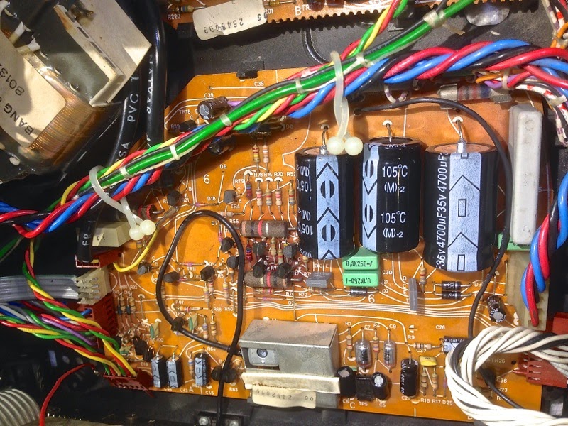
Today I went on to rebuild the power supply board (#6) of the current Beomaster 8000.

Here is a picture before replacing the electrolytic caps:


The big yellow cans often are out of spec at this age. In this Beomaster, however, they showed reasonable ESR and capacitance values....nonetheless out they went with all the other electrolytics. Here is a pic after putting in quality 105C caps:


I cleaned all the headers on the board and coated them with DeoxIT D100. Then I plugged everything back together, and the Beomaster came on without fuss. I hope the Mundorfs will soon arrive that I can replace the main reservoir caps to put this Beomaster fully on a solid footing.

Saturday, August 2, 2014

Beomaster 8000: Restoration of the Output Amplifiers

As usual, I rebuilt and tested the output amplifiers (PCB #5) of the current Beomaster 8000 restoration project before turning it on the first time. While the ebay seller claimed it was 'fully working' there is always a chance that one of the output trimmers goes non-contact during transport, i.e. in my opinion it is worthwhile to do the outputs first and test them with external power supplies (see here for a description of the process: http://beolover.blogspot.com/2011/09/output-stages-testrecap.html).
This takes a bit longer, but definitely saves a lot of cost and effort compared to replacing the output transistors. Anyway, here are the before and after pictures...:

Left amplifier before: 


after:


Right amplifier before:


after:


It was definitely a good idea to replace the caps, most were cracked. Here is a picture of one of the 220uF caps:


I measured the capacitance and ESR of these caps, and they were still all in spec...pretty amazing, considering the cracks...it seems the capacitor situation depends a lot on how the individual Beomaster was stored/treated, and whether it was used regularly etc...

When testing the boards, the external power supplies showed the following currents after adjusting to 18 mV for both boards:

+54V--> 0.10A
-54V-->0.11A
+15V-->0.01A

This all made sense, so I reconnected the output rails and fired the Beomaster up. It came on with a healthy double relay click and then showed a nicely working display. It seems all segments are working - also pretty amazing, considering the 'white PCB' style of the displays. I guess it was really treated well in its pre-eBay life!
I easily tuned into my favorite local radio station and enjoyed a bit of their NPR programming. The only issue I could find during this brief first test was a not working 'filters' light...hopefully this is just a light bulb.

On to the power supply.