Featured Post

Beolover SyncDrive: DC Platter Motor Replacement for Beogram 4002 and 4004 (Type 551x and 552x)

Late Beogram 4002 and the 4004 (Types 551x and 552x), which have DC platter motors instead of the earlier synchronous AC motors usually suff...

Showing posts with label reservoir. Show all posts

Tuesday, February 5, 2019

Beogram 4004 (5526): Repair of Record Detection Circuit and a New Reservoir Capacitor

I started working on the Beogram 4004 that I recently received. I decided to look into the 'does not lower arm at LP set-down point' issue first.

***I recommend downloading the Beogram 4002/4 service manual with the circuit diagram for reading this post.***

Usually, when a 400x Beogram does not stop at the LP point after pressing START (with a record on the platter), there are two standard causes:
1) It does not detect the record properly, or
2) the carriage position sensor does not work.

#2 is easily eliminated by watching if the deck switches to 45 RPM once the arm sweeps past the 7" singles setdown point. If it does, the position sensor is most likely up to the task.

The 4004 did the 45 RPM switch, i.e. it was time to look into the record detection circuit. The record detection circuit essentially needs to pass three tests:

1) Does the light bulb in the sensor arm work, and is it the correct bulb with the right current draw?

2) Does the platter induce a proper ~5.5-6V amplitude signal at the collector of TR3?

3) Does the circuit put out the proper signal at the collector of TR6 (~15.5V when there is a record; ~0V when there is none) when a record is on the platter?

Since the light bulb was working (lit B&O logo), I measured the voltage at the Collector of TR5 that drives the bulb and it showed 8.5V (spec is 9V, but that is o.k.). This voltage is used by the circuit to put out a 'no record present' signal when the bulb is dead (the voltage would be close to 21V in that case, which would permanently turn on TR6, i.e. its collector would be 0V - saying 'do not lower the arm'. This is a safety feature, since without it a dead bulb would give the sensor the same impression as the presence of a record, and the arm would be lowered on the platter.

With regard to #2, it is a good idea to check the DC voltage at the collector of TR3 first and measure if it is close to the prescribed 4V. This voltage is necessary to ensure that the sensor signal has a 6V amplitude when the ribs of the platter pull by beneath it. I measured 2.1, which was very low. This meant I needed to replace the biasing resistor R26 with a 2M trimmer for adjusting the bias of TR3 (in essence quench some of the CE current to achieve a higher C voltage). This is a very common issue in the 400x, and implanting the trimmer usually allows adjusting the bias to get 4V at the collector. I put in the trimmer and tried to adjust the collector voltage:
Unfortunately, even by completely maxing out the 2M resistance on the trimmer, I was only able to get to 3.4V. This meant that TR3 had an unusually large Hfe. In absence of an even larger trimmer (and the rule of thumb not to use large resistances/very small currents in such circuits if one can avoid it) I decided to put a new BC547B transistor in. This fixed it:
I measured the Hfe values of both transistors, and the original 548C had about 750, while the Hfe of the new one was only 430, which allowed the 2M trimmer to do its job.

While it was a good idea to fix the TR3 voltage, this was unlikely to have fixed the issue, since a too small sensor signal causes the opposite effect: It always detects a record whether there is one or not, i.e. the arm gets lowered onto the platter if there is an issue with the sensor signal.

The next step was to check on the output of the detection circuit, i.e. I needed to measure the voltage at the collector of TR6 when the carriage reached the setdown point. I did, and the voltage remained close to 0V, indicating that the circuit was not doing its job. First I thought TR6 was bad, but my transistor tester gave it a passing score. This meant something else was pulling the voltage down to zero.

I started the Beogram without TR6 in place. This essentially should tell the circuit "record present" since this causes the same situation like a turned off TR6. I measured the voltage again at the vacant collector terminal of TR6...and it was close to 0 volt again! So clearly there was a short somewhere. The most direct connection to 0V is probably via a shorted out C19 that would pull the collector pad down to ground via R41. I measure the capacitance of C19 in situ with my BK Precision 879B LCR meter, and it yielded 4.7 Ohms! This caused me a bit of head scratching, since there is essentially no other good path for this short circuit to happen in this circuit. I finally measured the resistance across C19 with my multimeter, and I got a stable reading of 132 Ohm! That should not happen with a working capacitor. So I took the capacitor out and replaced it with a new one. And the circuit worked again.

I thought this capacitance measurement was an interesting lesson. I measured the cap with my multimeter's capacitance setting, and it showed 0F. So it seems that the frequency based measurement method has hits weaknesses, when it comes to measuring borderline dead capacitors. The 879B did show an ESR value of 11 Ohm on this capacitor, which is very high. This should have tripped me off right away, but in the fog of battle...anyway, an enjoyable evening with a Beogram 4004 is coming to an end!...;-).

But wait, this Beogram had one more issue to rectify: The reservoir capacitor. Whoever tried to fix it before hot-wired a new reservoir cap of the cheapest kind into the unit:
I replaced it with a Beolover capacitor assembly that fits precisely under the mounting strap of the original one:
Beolovely again!


Monday, April 23, 2018

Beogram 4002 (5513): Restoration of the Main PCB and Installation of a Biasing Trimmer for TR3

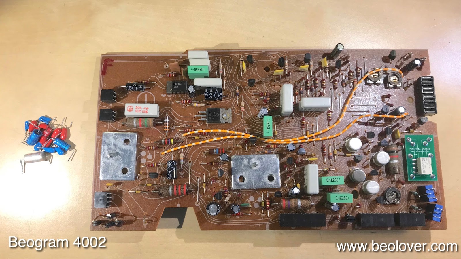
After restoring the basic functionality of the Beogram 4002 (5513) that I am restoring right now, it was time to complete the restoration of the main PCB and install a trimmer to properly bias TR3, which is responsible for the amplification of the record detection sensor signal. This shows the board as I received it:
My customer already had replaced the RPM relay and trimmers. I completed the job by replacing all electrolytic capacitors,
and by installing a trimmer that allows the adjustment of the bias at the base of 
TR3. This shows the trimmer temporarily installed on the backside of the board allowing adjustment while the board was installed/powered up:
Once the collector DC voltage was set to 4.0V, I installed the trimmer on the component side:
The original design has a fixed resistor in place, which in most cases results in too low amplification due to unpredictable variations in the current gain of the transistor placed as TR3. Proper amplification is important to prevent damage to the needle when the deck is accidentally started without a record on the platter.
Once this was done I updated the installation of the replacement reservoir capacitor assembly that also had been installed already:
On to the installation of a LED in the sensor arm...


Thursday, December 7, 2017

Beogram 4000: Restoration of the AC Motor and Replacement of the Reservoir and Motor Capacitors

After restoring the PCBs of the Beogram 4000 that is currently on my bench it was time to look after the reservoir and motor capacitors, and the AC motor itself. This shows the capacitor and motor section of the deck in original condition: 
I started removing the old cans and found that the big ones had started leaking:
So it was definitely high time to get this done. This shows the capacitor bay after removing them:
I also removed the motor (this was a good moment since its leads were already unsoldered from the capacitors):
The motor is held together by threaded rivets. If one wants to open the motor to re-lubricate the bearings, these rivets need to be drilled out. This is how the motor looked like after returning from my drill press:
I opened it up
A very simple yet elegant construction! Made in Switzerland...those were the days...;-).
This is a close up of the rotor with everything that sticks on the shaft:
I immersed the two halves of the motor housing with the bearings in oil (it seems there is no obvious way to get the bearings out without doing major damage) and pulled a vacuum to draw oil into the bearings.
I have actually at this point no evidence that these bearings are indeed Oilite bearings. It seems no significant bubbles form after the vacuum is up. But the treatment has so far permanently cured all motors that were knocking, so I am continuing doing it....
While the bearings were in the oil I installed my capacitor replacement assembly:
It consists of a 3D printed plastic shell that holds the new capacitors in place, and that fits into the mounting strap of the original capacitor assembly:
The motor was reinstalled using two 3D printed 'nut arresters' that are used to replace the drilled out threaded rivets, that allowed to adjust the tilt of the motor relative to the platter axis (this allows to adjust the height at which the belt sits on the platter):
These plastic parts hold the M3 nuts in place that one can adjust the tilt screws agains the motor housing:
I also usually replace the original slotted adjustment screws with modern stainless hex socket head bolts. They make the tilt adjustment so much more straight forward when the platter is installed since one can use a ball end hex screwdriver at an angle turning them while the platter is rotating.
Unfortunately, in the meantime I had to realize that the MMC cartridge mount of this Beogram has the (frequently found) cracked MMC cartridge mount, so the next step is to replace it with one of my (you guessed it!...;-) 3D printed replacements.


Sunday, June 4, 2017

Beogram 4000: Replacing the Reservoir and Motor Electrolytic Capacitors

After gold plating all of the switch terminals in the Beogram 4000 that I am restoring right now, it was time to rebuild the electronics. I usually start out by replacing the old reservoir and motor capacitors that are often out of spec and on the brink of failure. This shows the original units:

A while back I developed a 3D printed capacitor fixture that holds the (smaller) modern replacements neatly in place:
This assembly is a drop in replacement for the original capacitors since it uses the same retaining strip:
On to the circuit boards.


Tuesday, January 3, 2017

Beogram 4000: Replacement of the Reservoir and Motor Capacitors

After rebuilding the carriage transport and arm lowering mechanisms it was time to look into the electrolytic capacitors of the Beogram 4000 that I am currently restoring. I always enjoy replacing the original reservoir and motor capacitors in AC motor Beograms, and the 4000 has quite an impressive array of large cans under the hood:
The first step was to remove the old capacitors:
A quick test with my BK LCR tester revealed two bad capacitors:
One of the 2200uF capacitors was completely gone (7.3 nF), while the other one had a reading of 1300 uF, also out of spec. The others still had some life in them, but of course they also had to go to make sure that this unit will run for a bunch of years without capacitor troubles:
The new modern 105C capacitors that I installed are held in place with a 3D printed assembly that neatly clamps under the original mounting strip that held the old capacitors together. Like all my B&O parts, the capacitor assembly is available to other enthusiasts. Just send me an email or use the contact form on the right. A more detailed post about this procedure with a wiring diagram can be found here.


Friday, November 4, 2016

Beomaster 8000: Step Three - Replacing the Main Reservoir Caps

No power supply restoration of a Beomaster 8000 is complete without also replacing the four big cans in the back. They are the reservoir capacitors for the output amplifier ±54V power rails. One 10000 uF capacitor per polarity and channel - massive! That gives the Beomaster 8000 its excellent output stability at 150W per channel. Awesome!
Here are a few impressions of my process:

This shows the original capacitors on the right side:

I unsoldered and pulled them out and replaced them with modern 105C grade Japanese units. As usual, modern capacitors are a bit more compact than 1980s types. That is why I use 3D printed adapters to fit them into the capacitor bays of the Beomaster 8000. This picture shows the original capacitors and the modern replacements with their 3D printed adapters:
The adapters and capacitors are available as a kit, just send me a message using the contact form on the right

After the installation it turned out that I broke off one of the resistors at the thermal switch for the right side:
This happens frequently when pulling out the capacitors, since the resistors are in the way, and they cannot take much bending. I replaced both resistors with new ones:
Then it was time to turn this 8000 around and do the left side:
After replacement:
After this I measured the capacitance of the original caps and of course they were out of spec (they usually are at this point):
4000uF is less than half of the specced 10000uF, but this would still have worked at moderate volume settings. But of course, the caps would have failed in the near future. So it was the right thing to replace them now for piece of mind. 

An then it was finally time to turn this Beomaster 8000 on for the first time:
And of course, one of the segments in the input display was a no-show. No problem, since I usually rebuild these displays anyway with SMD LEDs to ensure stability in the years to come. These displays all will fail in the near future, i.e. it is almost better to buy a Beomaster with failed display for less money and then fix it. That way one has a Beomaster with displays that will likely last another 30 years.

On to recapping the rest of the unit!


Wednesday, November 2, 2016

Beomaster 8000: Step Two - Rebuilding the Power Supply

In electronics you usually have three things, power supply, high current loads and small current signal circuits. The smoke typically occurs when high current loads go haywire and then overpower the supply. That is why in every Beomaster 8000 that crosses my bench I first rebuild the output amplifiers. They are the main power consumers in the 8000, and therefore have the 'means' to cause significant trouble. Once the load side is reasonably stable, it is time to make sure that the supply side is sound, too. Bad reservoir capacitors can cause short circuits, and that often leads to smoke, too. Another frequent issue with supplies is that poor reservoir caps cause significant ripple, which can cause hum or microcontroller malfunctions. So here we go: Step 2 - rebuilding the power supply:

This shows the power supply board in its original condition:
And after replacing all the electrolytic capacitors with 105C grade Japanese units:
I checked the reservoir caps, and it turned out that one was on the verge of going out of business. Its capacitance was less than 1/3 of its spec:
This means that the other caps are likely not far behind, and that replacing them is a necessary step for trouble free operation down the road. After this 'satisfying' measurement, I put the board back in:
The next step is to replace the main reservoir capacitors for the ±54V rails. And then the power end of things should be good again.


Wednesday, September 14, 2016

Beogram 4002 (5501): Replacement of Reservoir and Motor Capacitors

The Beogram 4002 (5501) that I am restoring right now showed some erratic behaviors that indicated potential power supply trouble. When it comes to power everything starts at the reservoir capacitors and so I decided to put that on a solid footing. Many Beograms of that vintage suffer from dried out electrolytic capacitors, and replacing these big cans is always a good starting point for a restoration of the control system.
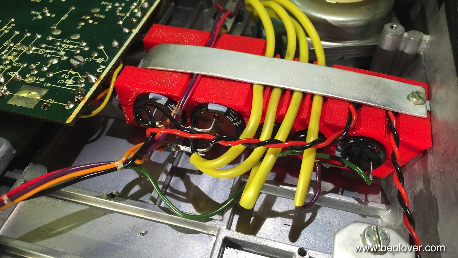
A look at the capacitors 'bank' of this early series 5501 immediately indicated that I needed to redesign my original 3D printed 550x capacitors fixture a bit to accommodate the thick yellow insulation tubes:
Here is the result:
I added the four deep 'half pipes' on the top part as seen here to make room for the insulation:
This allowed a neat installation:

Beautiful! Isn't it??
After I was done I checked the original 4000uF cans. Both were similarly out of spec:
While 2800uF for a 4000uF unit is clearly not acceptable indicating that the capacitors were on their way out, the new capacitors did not cure the erratic behavioral issues of the deck. So there must be something else amiss...on we go!...exciting! I always enjoy it if there is a previously unexperienced issue that one can try figuring out! This is Beolove!...;-)


Monday, November 23, 2015

Beogram 4000: Installation of New Reservoir and Motor Phase Capacitors Using a 3D Printed Adapter

It was time to replace the big capacitors in the Beogram 4000 that I am rebuilding right now. I always enjoy this procedure, especially due to the clean install enabled by my 3D printed adapter. It accommodates smaller modern capacitor units, while giving the entire set-up an organized look. I made an earlier post that shows in detail what leads are connected where, in case you get confused while doing this procedure...there are a quite a few jumpers to re-solder...;-).

Here is a picture of my capacitor kit with adapter (this is available to other enthusiasts - just send me an email). The two back-to-back caps on the left replace the original bipolar AC motor phase capacitor. The adapter has notches that fit to the original capacitor mounting strap holding everything firmly in place:

I used this kit to replace this fairly messy original set-up:

This is how it looks now after installation:

And here a detail picture of the connections:

On to recapping the PCBs and adjusting the motor trimmers.