Featured Post

Beogram Commander Remote Control: Maybe This is the Final Version!..;-)

This is a follow up to my recent post about the redesigned Beogram Commander remote control board, which now works in both (DC-motor) Beogr...

Saturday, July 31, 2021

Beogram 8002 From North Texas: Testing the restoration work so far

This Beogram 8002 is ready to do some testing of the restored components before starting in on the service manual adjustments.

The recapping of the circuit board, transformer and chassis capacitors was completed in the previous post
There aren't any capacitors in the button control panel but there are two LDR devices plus a lamp that will need to be adjusted during the service manual checks. On rare occasions those LDR devices and the lamp require replacement but I usually leave them alone. However, I do like to install a small test connector that is handy to use in testing the functionality of those two LDR devices.

Here is the Beogram 8002 button control panel removed and looking at the underside.
The photo shows the two adjustment screws for the LDR devices. Unfortunately there are not easily accessible test points for measuring the LDR voltages while doing the adjustment.


There is a small set screw and plastic tabs that keep the circuit board in place on the panel. You have to be careful in removing the board as I have come across quite a few panels where the plastic tabs are broken off...likely by someone that didn't know what they were doing.


Turning the circuit board over I noticed that the chassis ground connection was loose.


I cleaned off the copper area and resoldered the wire.


The LDR adjustment calls for measuring the two LDR devices (reverse and forward) to ground so I will add a small 3-pin connector with those signals.


The test connector is a female connector so there are no exposed pins to short out when the test connector is not being used. When I make the LDR service manual adjustment I will insert a 3-pin male plug for my testing.


I also plan on measuring the various Beogram 8002 sensors with an oscilloscope so I soldered on some temporary test wires for those signals on the back of the main PCB.


That takes care of what I will need for electrical measurements while testing the Beogram.
Now I just need to reassemble the tonearm assembly in the floating chassis.

I had removed the tonearm assembly for cleaning and lubricating the Beogram.  
I cleaned off all of the old lubricants and am ready to apply new lubricants to the Beogram 8002 spindle and tangential arm assembly rails.


You will notice that the rear rail is longer than the front rail and has a rubber sleeve (with a metal end cap) on each end. This type of rear rail is only on Beogram 8002 models that were built for markets where the AC line is 60 Hz. Bang & Olufsen engineers determined that the 60 Hz models were susceptible to some vibration that needed damping.  This is a USA model Beogram 8002 so it has the rear rail built with the damper. Because these turntables are over 30 years old I always clean and put some rubber conditioner on the ends.


To lubricate these parts I use some Tri-Flow synthetic grease on the mounting points of the spindle followed by a mixture of Rocol MTS 2000 and ESSO NUTO HP32 (1:1 ratio) on the spindle itself. On the front and rear rails that the tonearm assembly slides on I use some Tri-Flow dry lube. I have also used white D.C. M-kote paste on the rails as I use on the Beogram 400x turntables.


While the tonearm assembly is removed from the spindle and rails there is one service manual check/adjustment to go ahead and make.

The horizontal parallelism adjustment screw is on the bottom of the tangential arm assembly. So it is not accessible when the arm assembly is installed.  

This adjustment is to line up the top surfaces of the tonearm and the fixed arm so they are even with each other. Here is a photo of the adjustment screw.


Another adjustment screw that is only accessible from underneath the tonearm is the screw that holds the tracking force slider control in place. Sometimes this screw can become loose and the tracking force slider slides too easily. Often drifting away from the setting an owner sets it to. 

While I have easy access to the screw I made sure it is securely in place and the slider does not move too easily (there should be a little bit of friction).


Reinstalling the rails, spindle, spindle nut and tonearm assembly requires a bit of maneuvering of the parts all at once but it isn't too difficult. The rear rail must be fit through the tonearm assembly base and through the bracket that attaches to the spindle nut. Obviously the orientation of the parts are critical as well.


Everything can now, gently be tilted over to fit properly on the floating chassis.


The tangential arm servo motor belt and the position, rotary sensor assembly can now be reinstalled.


I can now start connecting floating chassis components together to see how the restored parts work.

A couple of quick checks are needed though.
Check that the center hub of the Beogram 8002 (with the tachodisk for the platter speed detection) spins easily and does not contact any part of the sensor assembly.  This one is good.


The top platter is not necessary for testing the basic Beogram 8002 functionality but the black, sub-platter is. The metal sub-platter passes between the curved slot of the two tangential drive motor components and is actually part of the motor. Without the sub-platter in place nothing will turn and the Beogram 8002 will try to drive the motor anyway ... and could blow a fuse.


Finally...here we go with the first power on test of the restored parts.
Everything that needs to be connected is connected.


You can see that the Standby dot is illuminated and ready to go.


Pressing play I get an operating platter, the tonearm assembly moves and the Beogram 8002 control logic is able to lock in the platter speeds.


As I expect to observe (and hear) the Beogram 8002 platter and tangential arm assembly operate extremely quiet and very smoothly.

That is it for this post. 
Next time I will measure the power supply voltages and view some sensor signals on the oscilloscope.
I will also finish up the service manual adjustments for the tonearm tracking force, record tracking and the forward/reverse LDR scanning voltages.


Monday, July 26, 2021

Beogram 8002 From North Texas: Replacing the electrolytic capacitors

Moving on to the electrical tasks on this Beogram 8002 project...
There are electrolytic capacitors in the Beogram 8002 in four locations: the floating chassis, PCB 1, PCB 2 and inside the transformer box.  Typically not all of them will be out of tolerance but it is a good move to replace all of them rather than wait for them to fail one at a time. 

I will start by showing the replacement of the two capacitors on the floating chassis.
These two, 0C1 and 0C2, are part of the Beogarm 8002 +5 VDC regulating circuit.


The two capacitors are easy to get to although the yellow, black and blue wires should be disconnected and moved out of the way first.

On this project the Beogram 8002's owner had already purchased a capacitor kit for it. The kit contains most of the capacitors I normally replace and they are good quality capacitors so I will use them.

Here are the new new 0C1 and 0C2 capacitors installed.


PCB 1 is the main board of the Beogram 8002 while PCB 2 piggybacks on top and inside a shielded, metal box.  


PCB 2 houses the Beogram 8002 microcomputer IC and has just one electrolytic capacitor to replace.
It is a difficult one to deal with though.  The negative lead side is soldered to both the top and bottom layers of the board. In addition, the space is a very tight fit and is right next to the microcomputer IC.

This lone electrolytic capacitor, 2C28, is for the +5 VDC supply voltage to the microcomputer IC...so pretty important :-).


I like to cut the exposed leads on the 2C28 capacitor to remove it first, then desolder and remove the remaining parts of the lead once I have more room.

This photo shows the other side of PCB 2 and the other two solder points of 2C28.


A number of years ago we started replacing the 40-pin IC socket for the microcomputer device on these Beogram 8000/8002 restorations.  Removing the old IC socket provides more operating room and the new 40-pin socket with tulip style contacts is a sturdier part than the original socket. It provides some extra insurance in reliability and is easy to replace during this capacitor replacement task.


The new 2C28 capacitor is in place and so is the new 40-pin IC socket.

I re-inserted the microcomputer IC (while taking electrostatic precautions of course).
I will apply new thermal paste to the top of the microcomputer IC later when I re-install the metal lid that has the heatsink for it.


One other step I performed on PCB 2 was to use a soldering tool to reflow the solder joints on all of the board connectors.  We have found that those connector-board solder connections can become faulty over time and they are not something a visual inspection can always catch. It is safer to just reflow the solder.

In case any Beogram 8000 owners are wondering, the microcomputer IC in the Beogram 8002 and Beogram 8000 are not compatible. The PCB 2 board and housing look the same but the functionality of the microcomputer IC itself is different enough where they are not interchangeable.

Next is PCB 1
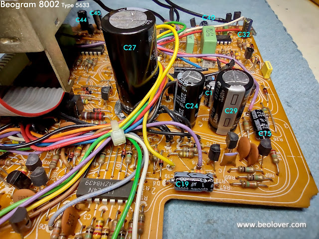
I used this photo above but I will include it again.  The photo shows all of the PCB 1 electrolytic capacitors that will get replaced except for the one hidden underneath the metal shield box.  I will show that replacement capacitor a little later on.


As I said earlier, not every electrolytic capacitor in the Beogram 8002 will be out of tolerance but there are always some that are...


Both of those capacitors are part of the Beogram 8002 power supply circuitry.

The largest capacitor, 1C27, which is for +15 VDC supply filtering was still in tolerance but it is being replaced now while all the other work is being performed.

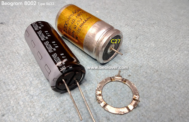
1C27 is a little unusual in that it has a three prong base for its negative lead.  The three prongs are for mechanical support and I have never found a modern replacement for this type of packaging.
The new capacitor is the common, two-lead, through-hole style of capacitor.


The Beogram 8002 PCB 1 board expects the 1C27 capacitor base to connect two of the board ground connections via that three prong base.  That can be accomplished with a jumper wire on the trace side of the PCB 1 or I can pop off the three prong base from the original 1C27 capacitor and re-use it.
I like to opt for the second option.


The new 1C27 capacitor positive lead goes right in the center of the three-prong mounting ring.
The negative lead gets bent around the mounting ring and soldered to it.


That is it. 
The new 1C27 capacitor will fit into the original PCB 1 holes and soldered in place the way the original was.


Here is that PCB 1, C28 capacitor that is underneath the PCB 2 shield box.


On PCB 1 on the other side of the shield box is 1C4.


That accounts for all of the PCB 1 electrolytic capacitors.
Just as I did on PCB 2, all of the PCB 1 board connector solder joints were re-flowed with solder.

The last electrolytic capacitor, 4C1, is a non-polarized capacitor located inside the transformer box.
The modern replacement capacitor is much smaller in its physical size so we created a 3D printed mount for it.


While I have the soldering tools out I took the opportunity to replace the audio muting relay on the Beogram 8002 output board, the small board that the 7-pin DIN connector is mounted to.

This is another precautionary change.  We have seen enough of these relays start to fail where it is safer just to replace them rather than wait for them to fail.

Here are the before photos.
I am including a picture of the trace side as it shows all of the wire connections for the phono audio signals.  The connections look really good on this Beogram 8002 output board. The last two Beogram 8002 output boards I worked on required re-soldering of those wires because they were poorly soldered and the connections were failing.  I expect the output board to always look like this one.


Here is the new Omron relay installed.


In the next post I will lubricate and re-install the tonearm assembly.

Thursday, July 22, 2021

Beogram 8002 From North Texas: A couple more cabinet repair tasks

As I was repairing the main PCB mounting post I couldn't help noticing the way this Beogram 8002's aluminum deck lid had been reattached. Like many repairs of these aluminum deck lids someone had used a foam type double-sided tape that is better suited for insulation. It is too thick for this application and results in a visible gap at the seam where the aluminum deck meets the Beogram cabinet frame.

I don't like that. Having the gap there would bother me.


I decided to pull the aluminum panel from the previous repair attempt and remount it correctly.

Here is the panel removed.  You can see the thick double-sided tape as well as the residue from the original B&O tape. All of that needs to be cleaned off and the surface prepared for some better 3M VHB tape.


When removing old glue residue I sometimes use paper towels soaked in isopropyl alcohol.  Most of the time though, I just use a product called Goo Gone.  It squirts onto the areas I want cleaned up and I let it soak for a few hours.


This Beogram 8002 also has a tonearm deck lid that still had the original B&O double-sided tape...now deteriorated.  So I added it to the cleanup mix.


Hours later I scraped the old adhesive material off all of the Goo Gone soaked surfaces.
That left me with a nice pile of goop.


The surfaces are clean now and ready for some good 3M VHB double-sided tape.


Here is the tape applied to the clean surface of the cabinet.
Note: Don't forget the small spring that fits between the deck and the aluminum lid. That is for removing electrostatic charge on the deck surface.


The aluminum deck fits nice and snug on the cabinet now with minimal gap between the cabinet and the aluminum deck material.


That is how it is supposed to look and is so much better than before.
Last is the reattachment of the two pieces that make up the tonearm compartment deck lid.

Two strips of VHB are applied to the surface of one of the plates, then they are fitted together.


Finally, here is the tonearm compartment deck lid back in place.