Featured Post

Beolover SyncDrive: DC Platter Motor Replacement for Beogram 4002 and 4004 (Type 551x and 552x)

Late Beogram 4002 and the 4004 (Types 551x and 552x), which have DC platter motors instead of the earlier synchronous AC motors usually suff...

Showing posts with label bracket. Show all posts

Saturday, July 31, 2021

Beogram 8002 From North Texas: Testing the restoration work so far

This Beogram 8002 is ready to do some testing of the restored components before starting in on the service manual adjustments.

The recapping of the circuit board, transformer and chassis capacitors was completed in the previous post
There aren't any capacitors in the button control panel but there are two LDR devices plus a lamp that will need to be adjusted during the service manual checks. On rare occasions those LDR devices and the lamp require replacement but I usually leave them alone. However, I do like to install a small test connector that is handy to use in testing the functionality of those two LDR devices.

Here is the Beogram 8002 button control panel removed and looking at the underside.
The photo shows the two adjustment screws for the LDR devices. Unfortunately there are not easily accessible test points for measuring the LDR voltages while doing the adjustment.


There is a small set screw and plastic tabs that keep the circuit board in place on the panel. You have to be careful in removing the board as I have come across quite a few panels where the plastic tabs are broken off...likely by someone that didn't know what they were doing.


Turning the circuit board over I noticed that the chassis ground connection was loose.


I cleaned off the copper area and resoldered the wire.


The LDR adjustment calls for measuring the two LDR devices (reverse and forward) to ground so I will add a small 3-pin connector with those signals.


The test connector is a female connector so there are no exposed pins to short out when the test connector is not being used. When I make the LDR service manual adjustment I will insert a 3-pin male plug for my testing.


I also plan on measuring the various Beogram 8002 sensors with an oscilloscope so I soldered on some temporary test wires for those signals on the back of the main PCB.


That takes care of what I will need for electrical measurements while testing the Beogram.
Now I just need to reassemble the tonearm assembly in the floating chassis.

I had removed the tonearm assembly for cleaning and lubricating the Beogram.  
I cleaned off all of the old lubricants and am ready to apply new lubricants to the Beogram 8002 spindle and tangential arm assembly rails.


You will notice that the rear rail is longer than the front rail and has a rubber sleeve (with a metal end cap) on each end. This type of rear rail is only on Beogram 8002 models that were built for markets where the AC line is 60 Hz. Bang & Olufsen engineers determined that the 60 Hz models were susceptible to some vibration that needed damping.  This is a USA model Beogram 8002 so it has the rear rail built with the damper. Because these turntables are over 30 years old I always clean and put some rubber conditioner on the ends.


To lubricate these parts I use some Tri-Flow synthetic grease on the mounting points of the spindle followed by a mixture of Rocol MTS 2000 and ESSO NUTO HP32 (1:1 ratio) on the spindle itself. On the front and rear rails that the tonearm assembly slides on I use some Tri-Flow dry lube. I have also used white D.C. M-kote paste on the rails as I use on the Beogram 400x turntables.


While the tonearm assembly is removed from the spindle and rails there is one service manual check/adjustment to go ahead and make.

The horizontal parallelism adjustment screw is on the bottom of the tangential arm assembly. So it is not accessible when the arm assembly is installed.  

This adjustment is to line up the top surfaces of the tonearm and the fixed arm so they are even with each other. Here is a photo of the adjustment screw.


Another adjustment screw that is only accessible from underneath the tonearm is the screw that holds the tracking force slider control in place. Sometimes this screw can become loose and the tracking force slider slides too easily. Often drifting away from the setting an owner sets it to. 

While I have easy access to the screw I made sure it is securely in place and the slider does not move too easily (there should be a little bit of friction).


Reinstalling the rails, spindle, spindle nut and tonearm assembly requires a bit of maneuvering of the parts all at once but it isn't too difficult. The rear rail must be fit through the tonearm assembly base and through the bracket that attaches to the spindle nut. Obviously the orientation of the parts are critical as well.


Everything can now, gently be tilted over to fit properly on the floating chassis.


The tangential arm servo motor belt and the position, rotary sensor assembly can now be reinstalled.


I can now start connecting floating chassis components together to see how the restored parts work.

A couple of quick checks are needed though.
Check that the center hub of the Beogram 8002 (with the tachodisk for the platter speed detection) spins easily and does not contact any part of the sensor assembly.  This one is good.


The top platter is not necessary for testing the basic Beogram 8002 functionality but the black, sub-platter is. The metal sub-platter passes between the curved slot of the two tangential drive motor components and is actually part of the motor. Without the sub-platter in place nothing will turn and the Beogram 8002 will try to drive the motor anyway ... and could blow a fuse.


Finally...here we go with the first power on test of the restored parts.
Everything that needs to be connected is connected.


You can see that the Standby dot is illuminated and ready to go.


Pressing play I get an operating platter, the tonearm assembly moves and the Beogram 8002 control logic is able to lock in the platter speeds.


As I expect to observe (and hear) the Beogram 8002 platter and tangential arm assembly operate extremely quiet and very smoothly.

That is it for this post. 
Next time I will measure the power supply voltages and view some sensor signals on the oscilloscope.
I will also finish up the service manual adjustments for the tonearm tracking force, record tracking and the forward/reverse LDR scanning voltages.


Saturday, May 19, 2018

Beomaster 6000 (2702) restoration: final assembly and testing

After some delay caused by the need to recoat the key panel (see update here), it is now finally time to finish the assembly and start testing the Beomaster 6000 quad after this full restoration!

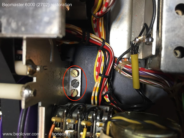
The display panel for the volume, tone and balance controls needs to be as close as possible to the red plexi panel for good readability. Therefore the frame on which the the display panel, motor controls, pulleys, clutches, tone amplifier PCB is mounted is adjustable. On each side on the frame there are 3 M3 bolts:  the middle one is to lock the adjustment and with the two other screws you can tilt and raise the frame.


Since you can not reach these bolts once the plexi panel is back in place, a different method is needed. I first attached the back black frame and the complete key panel to the main chassis. This was to have a reference point for adjusting.


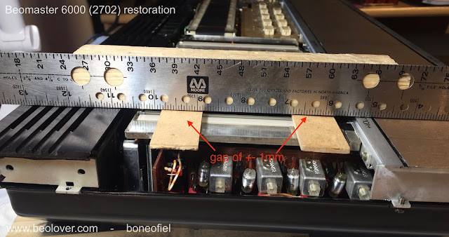
I used a metal ruler and some pieces of wood (with the same thickness as the plexi panel) to make the adjustment.


An air gap of about 1mm is sufficient to leave enough room for the display bands to move freely and avoid rubbing.


Once this is done the keypanel temporary screws are removed and the plexi panel is put in place. The next step is to attach the wood plinth and the keypanel.


One last adjustment, before tightening the keypanel and the wood plinth, is the centering of the FM dial spindle/flywheel. This is needed because the keypanel had been removed for coating and glued back. There is always a bit of play. The spindle is rotating in two ball bearings. The top one is fixed in the square plastic holder just under the spindle. The square plate first need to be centered by loosening the 4 M3 nuts.


The second ball bearing is inside the shaft bushing at the bottom. This ball bearing is in a metal bushing that is adjustable with 3 bolts. If you loosen these 3 bolts the whole spindle can "wobble" a bit and allows to have the spindle surface flat and centered with the surrounding aluminium frame. This can only be done once the keypanel with the wood plinth is firmly fixed.


And finally the wire bracket is put in place.


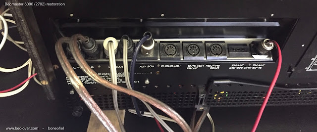
Time for testing ! I attached 2 Beovox S45-2 as front speakers and 2 Beovox P45 as rear speakers. I also attached an Airplay device to play some music from my iPad.


And I had sound on all 4 speakers !!!!! 


A reflexion after this many, many hours of careful restoration of this iconic Beomaster 6000 quad: it's not a job for the faint of heart ! Was it a succes? Yes, definitely. Does it look and sound good? It sounds sweet to my ears. And it looks as good as one can imagine after some 40+ years of use. I've been at the Bang & Olufsen museum in Struer, Denmark, where there is (off course) one of these units on display (and fully operational). See picture below. And honestly, mine looks better ! 

I will now let it play for some days/weeks before I'll ship it to his new owner. 


Above picture is courtesy of the B&O Museum in Struer, Denmark.

Saturday, April 8, 2017

Beogram 3000 (5228): Restoration of the Plexiglass Hood - Repair of a Cracked Hinge and Installation of 3D Printed Mounting Brackets

A while ago I received a Beogram 3000 with a deteriorated plexiglass hood. The plastic mounting brackets of the hood were broken out
and one of the plexiglass hinges was broken off:
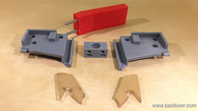
I developed a repair kit containing 3D printed mounting brackets, a special tool for re-inserting the spring tensioning block, and laser cut plexiglass patches for rejoining the hinge:
The video below shows how to use the parts. Like all other Beolover parts, this repair kit is available to other enthusiasts. Just send me an email or use the contact form on the right. Enjoy the video!

Saturday, April 2, 2016

Beomaster 4000 (2406): Installation of Custom Designed Toroid Transformer - Final Impressions

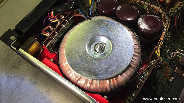
I finished up the toroid transformer implantation in the Beomaster 4000 that I am currently restoring. I added a bolt to fix it in its 3D printed cradle and used the mounting plate and rubber shock absorber that came with the toroid to secure it in place. Here is an impression:
Lovely! A very happy look in my opinion! 
Then I put on the bottom plate:
and with plate installed:
This shows a the detail around the 'gills' of the Beomaster:
I like how the red shines through a bit. Since the toroid represents a performance upgrade of the Beomaster and brings its power supply into the current millennium, I like that it can be seen a bit if closely scrutinized. Putting in a toroid into a Beomaster 4000 is a bit like installing Brembo calipers on a vintage BMW 5-series, if you catch my drift...;-):
Toroids have a much improved EMI performance than conventional "EI" style transformers due to their geometry. That is the main reason why most modern low noise analog power supplies employ toroid designs.
While I am writing this post I ran the unit together with the Norwegian Beogram 4000 that I am testing right now, and I can report that it sounds absolutely awesome! No humming on any input and everything stays absolutely cool including the toroid and I am cranking it up quite a bit right now. Appropriate for Jethro Tull's Aqualung!
This pretty much concludes the restoration of this Beomaster (if nothing comes during the testing period). Here is a picture of the units with exchanged parts:


Friday, April 1, 2016

Beomaster 4000 (2406): Exchanging the Electrolytic Capacitors and Adjustment of the Quiescent Current

After testing the new toroid transformer for a while (and coming to the conclusion that it works very nicely - no hum in the amplification chain whatsoever) it was time to complete the restoration of this Beomaster 4000 and replace all electrolytic capacitors on the various PCBs with new 105C grade major Japanese manufacturer units. While time consuming, this is not too difficult to do, but a few of the capacitors are challenging to access since the 4000 is from a time when board-to-wire connectors were not commonly used in consumer electronics. In other words, it is difficult to take out boards since most connections are soldered. So it is best to just leave everything in and work your way around a few obstacles like the power switch that obscures a solder point or the vertically installed loudness board. But with a bit of patience, a few tricks and a steady hand it is a straight forward process. Here are a few impressions. The first step is usually to take out the preamplifier board that is directly bolted to the frame with four screws next to the DIN jacks on the back. This picture shows the board in its original state:
And after exchanging the capacitors:
Then it was time to work on the two main boards. Unfortunately the preamp board does not disconnect like in the Beomaster 4400 where a rare wire-to-board header allows this convenience. In the case of the 4000 the board needs to be left connected and dangling from the frame while one works on the main PCBs. But this is not such an issue if one props up the Beomaster vertically using a couple of carpenter clamps affixed to the heatsinks (use cardboard shields to prevent scratches).

This shows the output amplifier board in its original condition:
The four red resistors at the bottom are the emitter resistors that can be used to adjust the quiescent current. In between them are the associated trimmers. I replaced these with modern encapsulated units along with the capacitors. This shows the board after restoration:
Next up was the FM tuner and 15V power supply board. this shows the original condition:
And after rebuilding it:
This board has two EMI cans. On the right is the FM 'front end' that selects the right carrier frequency and on the left is the 'detector' that converts the frequency modulation audio information into amplitude change that can be amplified and analyzed into an audible stereo signal. Unfortunately there is one electrolytic capacitor in each can and so one needs to get in there. The easy one is the front end, where the top and bottom covers come off easily. Note that the bottom one has a soldered ground connection which needs to be unsoldered before it can be taken off:
This shows the solder side of the PCB after taking the bottom cover off:
And here is a peek into the top:
The capacitor is in the top part, a brown/black tantalum type. This shows it replaced:
Care needs to be taken to not disturb the inductors. If they get accidentally 'adjusted' one may need a FM signal generator to recover. After putting the covers back on I turned my attention to the detector. Here the board is piggybacked on top of the main FM board and so one has to unsolder it first before the bottom of the PCB can be reached for soldering. The top cover can simply be pulled off. This is how it looks after it is off:
Then I took the board out:
The capacitor is up front center (also brown/black; 10uF). Before one can unsolder it the bottom shield needs to be taken off. One of the pins is soldered into the PCB, making the ground connection, i.e. it needs to be unsoldered first. Then the shield comes off:
And then I was able to put the new capacitor in:
After putting everything back together in reverse I took this picture:
On to the loudness board that is right behind the loudness switch on the front panel. There are two capacitors (red):
I should have replaced them while the transformer was out, but it did not occur to me. So I did some 'artistic soldering'. Copper brain is very useful for such situations when the desolder gun is too big to fit. After a bit of effort I had them out and replaced with new units:
Alright! Almost done. On to the FM preset capacitors that are soldered directly to the preset switches and a ground wire:
I also replaced them with new units:
The next step was to adjust the quiescent current with the new trimmers:
I elected to ignore the prescription of the service manual to measure the current in the output transistors directly with an ampere meter connected into the circuit. The setup allows for that via two pin headers that are not soldered. However, I did to like the idea to connect a multimeter with an internal resistance of about 5 Ohm in mA mode into the circuit and thereby altering the setup. I instead calculated the current that corresponds to the prescribed 80mA quiet current in the 0.15 Ohm emitter resistors in each of the B-style push-pull output branches (12mV), and hooked up my multimeter across these resistors and adjusted the trimmers to get the 12mV. Now this Beomaster is running cool. When it arrived one of the channels got pretty warm indicating trimmer issues, as they are frequently found in this vintage of B&O.