I recently received a Beogram 4000 that I restored in 2020 for a repair: The solenoid occasionally started oscillating after arm lowering was initiated, either via the ON function or when pressing the arm up/down buttons.
When I opened the unit, however, I immediately saw a more pressing situation that needed immediate attention: The wiring sleeve of the carriage harness was completely shredded, exposing the wiring:

I removed the carriage and turned it around:

This was a first for the Beolover! Luckily, the wires themselves still seemed undamaged. In a way it was great timing for the solenoid to develop issues. Had this wiring harness seen more carriage travel, most likely one or more of the wires would have been damaged.
The challenge with replacing the sleeve is that all the wires that go through it need to be disconnected that the replacement can be installed. There are quite a few wires going to the carriage! Nine of them connect directly to the circuit board that is bolted to the carriage:

And then there are the separately 'bundled' wires to the tone arm and the sensor arm in their yellow and grey sheaths. They connect to a terminal board behind the main carriage PCB:

Since this project was a first, I decided to spend some time cataloging the wiring for future reference. I added these two slides to my Beogram 4000 reference:


Wiring harnesses are fun!...;-). Then I started taking things apart. First I removed the solenoid switch to gain some work space around that small terminal board. It is always a bit challenging to use a soldering iron in this area due to the 'high density wire-spaghetti', which makes damaging insulation very easy. After I removed the solenoid switch I found it drenched in oil and caked with sleeve fibers:

At this point I assumed the oil was the reason for the occasionally oscillating solenoid (it was not...;-): If the ground connection through the solenoid switch is poor, the solenoid may not get enough current to fully engage and then it snaps back and tries again etc...i.e. it oscillates. If you look closely in this picture you can see the oil meniscus between the two switch terminals:
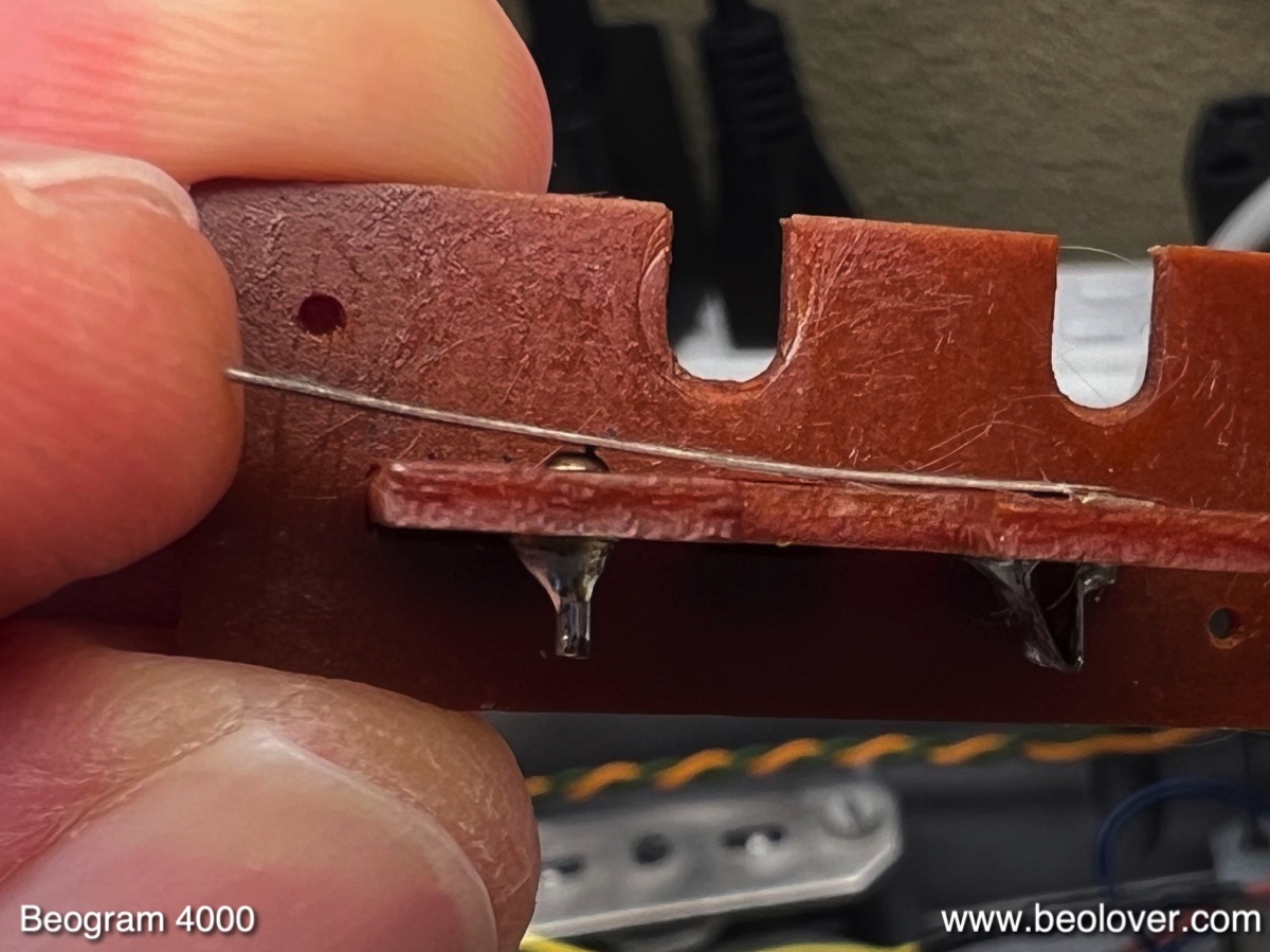
Since most oils are insulators, this caused an inconsistent resistance across the closed switch ranging from 0.5 to ~3Ohm depending on the particular actuation of the switch. I disconnected it

and then cleaned it in isopropyl alcohol with an ultrasonic cleaner:

After the clean, the resistance was back to close to zero, as it should be with directly connected test leads:

The I proceeded to disconnect the entire harness:

This shows how the soldered-in clamp secured the original harness at the carriage side:

and at the other end:

Opened up:

I removed the clamps

and measured the length of the sleeve as good as I could considering its state. It seems it is about 160mm long:

I very carefully cut the sleeve remnants open with a pointed crafts knife:

This shows the removed sleeve mess

and the liberated wires:

I cleaned up the sleeve fragments and secured the three separate wiring groups with shrink tubing to help with feeding them though the new harness:

I blasted the ends of the tubes briefly with hot air to secure them in place:

I bought some 1/4" internal diameter braided expandable polyester wire sleeving. This type of sleeving can expand its diameter by a factor 2-3, making it possible to feed wires through it. The challenge is to keep the wire expanded while the wires are being fed through. After some trial and error with makeshift rolled paper tubes and other makeshift ideas, it turned out that a tube with a severable pointed tip works well. I designed a thin tube with a tip that can easily be broken off and 3D printed it:

This tube was easily inserted into the braided sleeve:

The next step was to cut the sleeve off at the tip end. After some trial and error it turned out to work very well with the hot air blower using a small nozzle:

The added benefit of this 'cutting technique' is that the plastic fibers will melt together at the end, which keeps the sleeve from unraveling (I did the same at the other end before I inserted the spreader tube):

It took me a few attempts with different tube lengths to arrive at the correct expanded length of ~160mm:

After this successful trial, I printed another tube and now put the wiring though the tube:

The I pulled the tube out and allowed the sleeve to expand:

From the 'expansion stress' the ends of the sleeve stayed a bit expanded. I took a page from B&O's playbook and tied the ends with some electrical tape, similar to what I found they had done with tape in the clamps that secured the original sleeve:

This made it easy to fix the new sleeve in place with the clamps:

At the other end I did the same:


Once the new sleeve was secured in place, I checked all wiring for continuity to make sure that there were no issues before soldering them back to their terminals:

And here the final result:

The new sleeve behaves very nicely when driving the carriage left and right. Beolovely! So this issue seems fixed! On to the oscillating solenoid issue!