Saturday, September 27, 2014
Beomaster 8000: Volume Wheel (Encoder) Damping - The Video
I really like my Beomaster 8000 with yesterday's volume wheel damping update! So I decided to implement the same approach in the 8000 that will go to Australia next week. Can't let it go less than perfect!...;-). I used this opportunity to make a short video about the procedure. Enjoy!
Friday, September 26, 2014
Beomaster 8000: Volume Wheel (Encoder) Damping - Better Solution
*********Note: There is an update to this entry where a 3D printed part is used as paddle wheel to increase the interaction with the damping grease*****************************************
I was not really happy with my recent Beomaster 8000 volume encoder damping restoration effort. So I tried a few more things on one of my own 8000s. I realized that the original damping must have been a very heavy damping grease to achieve a sensible damping of the volume wheel. I ordered a sample kit of damping greases from Nye. I tried out their highest viscosity type, 868VH, but this still did not yield a damping as strong as I would have liked it.
After some deliberation, I realized that torque is the issue, and I decided to increase the radius of the encoder shaft for a higher damping force. I found a piece of 3 mm silicone sheet in my stash, and I drilled a 3 mm hole into it, and then cut around it:

The irregular shape results in some added turbulence in the grease. When installed the piece spun freely on the encoder axis, i.e. did not rub significantly on the grease well housing. This ensured a smooth rotation-feel of the encoder, only damped by the viscosity of the grease.
Here are the pics after installing the silicone piece and adding the Nye 868VH damping grease:


I pushed the grease in with a toothpick. Then I installed the cover and wiped the excess grease off:

It is important to adjust the screw properly to hold the wheel in a position flush to the panel surface when it is installed horizontally. Make sure that the wheel does not scrape the housing when turned. The above procedure yielded a damping which reduced spin to about 0.5 rotation when giving it a pretty hard spin. Let's see how this repair fares over time....
I was not really happy with my recent Beomaster 8000 volume encoder damping restoration effort. So I tried a few more things on one of my own 8000s. I realized that the original damping must have been a very heavy damping grease to achieve a sensible damping of the volume wheel. I ordered a sample kit of damping greases from Nye. I tried out their highest viscosity type, 868VH, but this still did not yield a damping as strong as I would have liked it.
After some deliberation, I realized that torque is the issue, and I decided to increase the radius of the encoder shaft for a higher damping force. I found a piece of 3 mm silicone sheet in my stash, and I drilled a 3 mm hole into it, and then cut around it:
The irregular shape results in some added turbulence in the grease. When installed the piece spun freely on the encoder axis, i.e. did not rub significantly on the grease well housing. This ensured a smooth rotation-feel of the encoder, only damped by the viscosity of the grease.
Here are the pics after installing the silicone piece and adding the Nye 868VH damping grease:
I pushed the grease in with a toothpick. Then I installed the cover and wiped the excess grease off:
It is important to adjust the screw properly to hold the wheel in a position flush to the panel surface when it is installed horizontally. Make sure that the wheel does not scrape the housing when turned. The above procedure yielded a damping which reduced spin to about 0.5 rotation when giving it a pretty hard spin. Let's see how this repair fares over time....
Monday, September 22, 2014
Beomaster 6000 4-Channel: Positioning the Indicator Bands
I finally had some time to continue the LED-ification project of my Beomaster 6000 4-Channel (several of the lightbulb fixtures had broken out tab-receptacles, and I did not want to use tape to fix them in place, so I decided to do it with LEDs)
I made some major progress on this today, and it seems everything is finally working. More about that after I do some more testing of this set-up.
I was confident enough to re-install (for the 4th time, I think...patience is a great asset with the Beomaster 6000...;-)) the indicator bands of the motor unit. I realized that I previously adjusted them slightly wrong in their position. So I wanted to share here how to do it right:
The small white dots in the indicator panel are meant to adjust the bands relative to the potentiometer position. This is how I aligned them this time before pushing in the clips (see here for details on the entire procedure and a video):

That's it for today...
Saturday, September 20, 2014
Beomaster 8000: Intermittent Display Digits - Bad Solder Joints
Oh well...While I was cheerfully listening to an episode of Car Talk on NPR on the Beomaster 8000 that will soon go to Australia, I could not help noticing a couple digits in the freshly restored frequency display fluctuating -on-off-on-off...Back to the bench with this one! It really is a nice workout, carrying the 45 pound behemoth to my electronics lab...;-).
The digits that blinked suggested a problem with the Phase 3 strobe that governs two digits in the frequency display, as well as the balance digit. I quickly found the problem: A broken solder joint at P74 that, among other signals, connects Phase 3 to pin 15 of 9IC3 (the master microprocessor). Here is a picture of the solder joints of the connector:

If you look carefully, you will notice the shadow around the leftmost joint...this indicates a broken out joint.
I re-soldered all jacks and plugs on the two joined PCBs and now all is fine. These two large, but poorly mechanically supported boards are really the most problematic area of the 8000s...whenever there is erratic behavior, it is usually some solder joints or vias on #8 or #9. I will add the re-soldering of the board-to-board connectors to my standard Beomaster 8000 restoration process. Live and learn!
Back to the living room for some more in the field testing before the long journey.
The digits that blinked suggested a problem with the Phase 3 strobe that governs two digits in the frequency display, as well as the balance digit. I quickly found the problem: A broken solder joint at P74 that, among other signals, connects Phase 3 to pin 15 of 9IC3 (the master microprocessor). Here is a picture of the solder joints of the connector:
If you look carefully, you will notice the shadow around the leftmost joint...this indicates a broken out joint.
I re-soldered all jacks and plugs on the two joined PCBs and now all is fine. These two large, but poorly mechanically supported boards are really the most problematic area of the 8000s...whenever there is erratic behavior, it is usually some solder joints or vias on #8 or #9. I will add the re-soldering of the board-to-board connectors to my standard Beomaster 8000 restoration process. Live and learn!
Back to the living room for some more in the field testing before the long journey.
Thursday, September 18, 2014
Beomaster 8000: Frequency Dial Not Working
Today one of my friends came over with his Beomaster 8000 in his arms...I restored this one a few years ago, so I felt responsible. The nice bottle of Napa cabernet that came with the Beomaster also helped...;-).
So I put it on the bench and opened it up. A quick test whether the infrared LED in the encoder is toast is by shining a flashlight into the encoder to temporarily 'replace' the LED. The IR receivers in the encoders are somewhat sensitive to white light, i.e. they work with a strong LED flashlight. If the encoder works with the flashlight, the LED is toast (see my entry about fixing these LEDs: http://beolover.blogspot.com/2012/07/beomaster-volume-encoder-repair.html)
In this case the flashlight did not do anything....so I checked the encoder outputs on plug P79. There I got the proper 5V square waves, i.e. the encoder was working.
The next step was to measure the signal at the Schmitt trigger (HEF40196B, 9IC7). The signal arrived there...so on to 9IC3, the master microcontroller. And bingo: no signal at pins 13 and 14. This meant that in both A/B signal paths from the encoder the vias died...
It occurred to me that back then when I fixed this Beomaster up, I did not yet routinely rework the vias on the microprocessor board (PCB #9) when restoring the 8000.
So, I re-soldered all the vias on the board (I assumed the others were probably also close to no-contact...), and everything was fine!
Friday, September 12, 2014
Beomaster 8000: Repair of a Broken Phono Jack with a 3D Printed Insert
The input jacks (sockets) of the Beomaster 8000 are weakly designed. They are made from a plastic that gets brittle over the years, and frequently the tabs that fix the jacks in the socket panel break off when a phono or tape plug is inserted. When that happens the jacks fall into the panel.
So far the remedy was to obtain a replacement from a carcass...a saddening thought. Beolover has a no-carcass policy! Parting out one should really be the very last resort!
Luckily, the 1980s designers of the jacks had a few looks too many at the cheap American cars that were made during this period (remember the Dodge Omni??), and that inspired them to also cheap down their design of these plugs.
To save plastic, they introduced recesses below the jack surface, which probably reduced the weight of the jacks by about 20%. It occurred to me that these recesses could be used to anchor a 3D printed insert, which would restore full functionality and get close to the original looks of the jacks. I made a brief video about the repair procedure (some pics are below):
The STL file of the inserts with printing instructions can be found on my website at www.beolover.com. I will also be happy to supply this part on request.
Here is a pic of the broken jack:

And with the 3D printed inserts in the recesses:

And after re-installing the jack together with the inserts:

It looks and feels pretty much like an original jack...there is a slight irregularity across the surface of the tabs due to the 3D printing raster. Oh well...it is never perfect! We can only strive!
Tuesday, September 9, 2014
Beomaster 8000: Wire Bridges on Microcomputer Board (#9) and Broken Phono Jack
Before I put the Beomaster 8000 back together for a test-drive in the living room together with his play-pals, the Beocord 9000 and the Beogram 8000, I cleaned and de-oxidized all the contacts on the microcomputer board (PCB #9), and had a look at the inner sanctum, the EMI shielded processor cans. Usually one needs to re-solder the few vias that are on this board, since they tend to be poorly soldered...clearly in the 80's the PCB technology was not that advanced, yet. Anyway, what I found in this particular Beomaster was remarkable. Someone already had put in the B&O recommended wire bridges (and then some...), and they were directly soldered to the processor pins. Unbelievable! Here is a pic:

While the soldering appears to have been carried out with some capability, I would never do it this way...the only parts of the Beomaster 8000 that are truly non-replaceable are the microcontrollers that contain proprietary coding, i.e. one would have to extract the code from a working one, if one would want to attempt replacing it with a NOS chip...
Anyway, clearly, this needs to be left as is. I could not risk to expose those rarefied microcontroller pins to another heat-cool cycle. In a way, since the chips survived this assault, this solution is probably the most reliable...several fewer spring based contacts in between the controllers and their slaves...so I decided to just replace the two electrolytic capacitors on this board and move on.
Here is a pic after putting in the caps:

The last thing that needs to get fixed in this Beomaster is a broken phono jack in the 'socket panel' that lost its tabs that prevent it from popping into the panel when trying to plug in the Beogram:

I am working on a creative solution, since not even Dillen of Beoworld.org has this part available. He said it is rare, since it often breaks...Another day, another 3D print...;-)
Saturday, September 6, 2014
Beomaster 8000: Volume Wheel (Encoder) Damping
********This is a historic post. Please, Check here for an updated procedure.******************
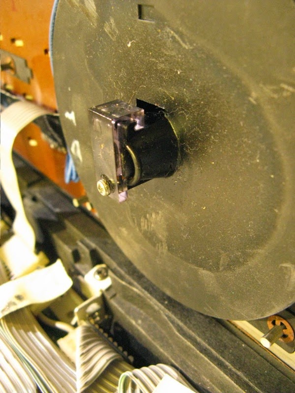
After the displays were back in the Beomaster 8000, I remembered that the volume encoder wheel had lost all its damping. The picture below shows the backside of the encoder housing (this is actually from another Beomaster, I forgot to take a pic of the assembled feature). Together with the plastic 'clamp' an O-ring seals a compartment where a viscous material can be inserted to dampen the rotation of the encoder. In the case of volume adjustment, this is desired to avoid any accidental 'dial-up' of the volume by the inertia of the fairly heavy metal wheel (think having a party with many happy people interested in your Beomaster...;-).
After the displays were back in the Beomaster 8000, I remembered that the volume encoder wheel had lost all its damping. The picture below shows the backside of the encoder housing (this is actually from another Beomaster, I forgot to take a pic of the assembled feature). Together with the plastic 'clamp' an O-ring seals a compartment where a viscous material can be inserted to dampen the rotation of the encoder. In the case of volume adjustment, this is desired to avoid any accidental 'dial-up' of the volume by the inertia of the fairly heavy metal wheel (think having a party with many happy people interested in your Beomaster...;-).
.jpg)
Geoff at Beoworld.org recently told me that he fixed the damping by putting in some high viscosity grease into the compartment, which worked great. So, I put in Silicone grease (which is the least problematic grease in terms of 'interaction with other materials', i.e. one can expect it to be inert in most settings). Here is a pic:

I also needed to replace the O-Ring. I used a Buna Nitrile 1/2"ID X 5/8"OD X 1/16"CS ring from theoringstore.com, which seemed to have about the dimensions of the old deformed ring.
This procedure resulted in a fairly well damped encoder.
Time to put the Beomaster back together!
Beomaster 8000: Display Restoration with SMD LEDs - Reassembling the Display Units
The SMD LEDs that I put into the Beomaster 8000 displays survived the 48 hrs test without problems. Time to put the display units back together. I applied the method I outlined earlier in this blog:
http://beolover.blogspot.com/2012/09/beomaster-8000-display-repair-hopefully.html
After I glued the transparency foil pieces to the back of the displays, I fixed them with carpenter clamps:

And after extracting them from the clamps:

Then I replaced R14 and R16 with 3.3kOhm and 1.5kOhm resistors to adjust the display voltage to reduce the intensity of the LEDs. See this blog entry for details about the adjustment procedure:
http://beolover.blogspot.com/2012/05/beomaster-8000-display-brightness.html
Then it was time to solder the displays back in. The insertion of the displays back into the board is tricky since one needs to line up all the pins at once...patience and calm music pays here...;-). Here is the display board after installation:

I adjusted trimmer R15 to get about 3.1V keyboard strobe (yellow) and about 4V on the LED rail (blue). It is important that the keyboard strobe does not go below 2.7V (see above blog entry for a discussion):

Looks like we are almost done. The last step before I put it back together is to check on the processor board.
http://beolover.blogspot.com/2012/09/beomaster-8000-display-repair-hopefully.html
After I glued the transparency foil pieces to the back of the displays, I fixed them with carpenter clamps:
And after extracting them from the clamps:
Then I replaced R14 and R16 with 3.3kOhm and 1.5kOhm resistors to adjust the display voltage to reduce the intensity of the LEDs. See this blog entry for details about the adjustment procedure:
http://beolover.blogspot.com/2012/05/beomaster-8000-display-brightness.html
Then it was time to solder the displays back in. The insertion of the displays back into the board is tricky since one needs to line up all the pins at once...patience and calm music pays here...;-). Here is the display board after installation:
I adjusted trimmer R15 to get about 3.1V keyboard strobe (yellow) and about 4V on the LED rail (blue). It is important that the keyboard strobe does not go below 2.7V (see above blog entry for a discussion):
Looks like we are almost done. The last step before I put it back together is to check on the processor board.
Wednesday, September 3, 2014
Beomaster 8000: Standby Issue - Beomaster Does Not Turn Back On During a 50 sec Window
Today I looked into a strange phenomenon I came across in the last Beomaster 8000 I restored. When no speakers are connected, or the speaker switches are in 'off' position, then the Beomaster would not turn on the output stages (i.e. no relay-click audible) if a turn-on occurs in a time window of 10-50 sec after turning it off.
This is not much of an issue in 'normal' operation, where one listens to some music, then turns it off, and comes back an hour later for more. But on the bench, when one tries out a few things and the Beomaster gets turned on and off in quick succession, and often without speakers attached, this phenomenon became quickly apparent.
This is the first Beomaster I encountered with this problem.
So I thought I would try to get to the bottom of this. The first thing is always to do some Googling these days. What came up was a Beoworld.org 'Vintage Products Forum' entry by Dillen/Martin where he states that:
"It's not uncommon to see that a Beomaster 8000 won't switch the amplifiers back on right after being put into standby. It will light up the displays but not power on the amplifiers.
Put back into standby for 15-20 seconds and it will power up fine again. This is quite normal."
In the particular case discussed here the Beomaster does come on during the first ~10-15 sec, and then not until about 50 sec have passed. After 50 sec it starts up again. The phenomenon is completely reproducible, but the speakers must be disconnected/switched off to experience it. When the speakers are on, everything is fine.
Anyway, I opened it up again today and did a few measurements with my oscilloscope (since this is a transient phenomenon, we need a time dependent measurements...). I fairly quickly identified the cause for the phenomenon: Pretty much the only way to prevent the outputs from turning on in a reproducible fashion is via the fault circuit:

Both right and left channels have a 'fault output' that triggers the 'Fault Switch' on the power supply board to cause a shutdown of the outputs in case a DC voltage is present at the speaker output, or if the temperature in the heat sinks gets too high. In either case a non-zero voltage occurs at the voltage divider between 5R24 and 23 (on the left...that part of the circuit is on the #5 PCBs (output amps), which is used as 'fault output'
I measured the voltage at that R23/24 point depending on the time after shut down with speakers connected. The yellow trace in the scope shot below is the positive 54 V rail which was used to trigger the measurement at 48.8V, i.e. a short while after turning off the Beomaster as the rail started to decay. The blue trace is the voltage at the fault output. So we see that there is a ~600-700 mV negative voltage spike that decays within about 10 sec to zero. This is not enough to trigger the fault switch because of 6R62, and everything is o.k.

An entirely different picture presented itself after disconnecting the speaker from that channel:

Note the now larger 1V scale for the blue trace, i.e. the initially still present small negative voltage spike seen with speakers connected in the scope shot above was completely overwhelmed by a ~4V positive potential when the speaker was disconnected. This potential boost was reset after about 45 sec and zero voltage remained at the fault switch at that point. This corresponds nicely with the ~50sec I measured that I had to wait to get the Beomaster to turn on again. It seems that after 50sec everything resets. This correlates with the delay when the microprocessor turns off the 15 V rails after shut down has been initiated.
It may be that there is a potential build up due to an inconsistency in the decays of the positive and negative 54V rails after turning the Beomaster off. This is no problem as long as there is a speaker connected, which provides a path to ground if there is some DC transient on the output during shutdown. Without speaker, the potential builds up, and the fault switch is triggered.
The real question is: Why do only some Beomasters exhibit this phenomenon, while others do not. I am aiming to do similar measurements on one that does not show this phenomenon, maybe we can learn something from that...
This is not much of an issue in 'normal' operation, where one listens to some music, then turns it off, and comes back an hour later for more. But on the bench, when one tries out a few things and the Beomaster gets turned on and off in quick succession, and often without speakers attached, this phenomenon became quickly apparent.
This is the first Beomaster I encountered with this problem.
So I thought I would try to get to the bottom of this. The first thing is always to do some Googling these days. What came up was a Beoworld.org 'Vintage Products Forum' entry by Dillen/Martin where he states that:
"It's not uncommon to see that a Beomaster 8000 won't switch the amplifiers back on right after being put into standby. It will light up the displays but not power on the amplifiers.
Put back into standby for 15-20 seconds and it will power up fine again. This is quite normal."
In the particular case discussed here the Beomaster does come on during the first ~10-15 sec, and then not until about 50 sec have passed. After 50 sec it starts up again. The phenomenon is completely reproducible, but the speakers must be disconnected/switched off to experience it. When the speakers are on, everything is fine.
Anyway, I opened it up again today and did a few measurements with my oscilloscope (since this is a transient phenomenon, we need a time dependent measurements...). I fairly quickly identified the cause for the phenomenon: Pretty much the only way to prevent the outputs from turning on in a reproducible fashion is via the fault circuit:
Both right and left channels have a 'fault output' that triggers the 'Fault Switch' on the power supply board to cause a shutdown of the outputs in case a DC voltage is present at the speaker output, or if the temperature in the heat sinks gets too high. In either case a non-zero voltage occurs at the voltage divider between 5R24 and 23 (on the left...that part of the circuit is on the #5 PCBs (output amps), which is used as 'fault output'
I measured the voltage at that R23/24 point depending on the time after shut down with speakers connected. The yellow trace in the scope shot below is the positive 54 V rail which was used to trigger the measurement at 48.8V, i.e. a short while after turning off the Beomaster as the rail started to decay. The blue trace is the voltage at the fault output. So we see that there is a ~600-700 mV negative voltage spike that decays within about 10 sec to zero. This is not enough to trigger the fault switch because of 6R62, and everything is o.k.
An entirely different picture presented itself after disconnecting the speaker from that channel:
Note the now larger 1V scale for the blue trace, i.e. the initially still present small negative voltage spike seen with speakers connected in the scope shot above was completely overwhelmed by a ~4V positive potential when the speaker was disconnected. This potential boost was reset after about 45 sec and zero voltage remained at the fault switch at that point. This corresponds nicely with the ~50sec I measured that I had to wait to get the Beomaster to turn on again. It seems that after 50sec everything resets. This correlates with the delay when the microprocessor turns off the 15 V rails after shut down has been initiated.
It may be that there is a potential build up due to an inconsistency in the decays of the positive and negative 54V rails after turning the Beomaster off. This is no problem as long as there is a speaker connected, which provides a path to ground if there is some DC transient on the output during shutdown. Without speaker, the potential builds up, and the fault switch is triggered.
The real question is: Why do only some Beomasters exhibit this phenomenon, while others do not. I am aiming to do similar measurements on one that does not show this phenomenon, maybe we can learn something from that...
Tuesday, September 2, 2014
Beomaster 8000: Rebuilding the Displays with SMD LEDs
I saved the final restoration task until the end. The Beomaster 8000 displays are one of the major trouble spots, and this Beomaster needs to survive a long journey to Australia. So we decided to rebuild all four display units with surface mount (SMD) LEDs to ensure that the displays will still work post-shipping.
As usual I took out the display board for easier access to the solder points of the displays:

It is advised to use a desolder gun for taking the displays out, since all display pins need to be loose before removal of the displays. Trying to do this with copper braid is not advised. So I took my trusted Hakko 808 to it and removed the displays:

Then I removed them from their plastic alignment supports:

And opened them up. this is done by cutting off the plastic tabs protruding out of the bottom of the circuit boards with a sharp knife (take care to not damage the traces...):

The next steps were to scratch off the old LEDs (here also caution is advised to not damage the traces). And then, after a thorough cleaning with ethanol it was time to solder the SMD LEDs on:


It is imperative that the LEDs are well-centered on the pads that the white reflector masks can fit on without straining the LEDs and without gaps between the masks and the circuit boards (otherwise, light will penetrate from below into adjacent, potentially off segments and make them light up partially...an ugly effect).
After I completed the job I set the displays up for testing on a breadboard. I usually run them for 48 hrs before putting the displays back together. I also test them for stability by trying to wiggle them with a toothpick left and right to see if the solder joints are good. One of the issues when soldering the LEDs is that the boards do not have a solder mask, hence the solder tends to flow away from the components, which can cause problems. This can be counteracted somewhat by heating the part first, then the pad, but nonetheless, this must be kept in mind during this procedure.

So far so good! I'll be back in a couple of days and let you know how this test went...
As usual I took out the display board for easier access to the solder points of the displays:
It is advised to use a desolder gun for taking the displays out, since all display pins need to be loose before removal of the displays. Trying to do this with copper braid is not advised. So I took my trusted Hakko 808 to it and removed the displays:
Then I removed them from their plastic alignment supports:
And opened them up. this is done by cutting off the plastic tabs protruding out of the bottom of the circuit boards with a sharp knife (take care to not damage the traces...):
The next steps were to scratch off the old LEDs (here also caution is advised to not damage the traces). And then, after a thorough cleaning with ethanol it was time to solder the SMD LEDs on:
It is imperative that the LEDs are well-centered on the pads that the white reflector masks can fit on without straining the LEDs and without gaps between the masks and the circuit boards (otherwise, light will penetrate from below into adjacent, potentially off segments and make them light up partially...an ugly effect).
After I completed the job I set the displays up for testing on a breadboard. I usually run them for 48 hrs before putting the displays back together. I also test them for stability by trying to wiggle them with a toothpick left and right to see if the solder joints are good. One of the issues when soldering the LEDs is that the boards do not have a solder mask, hence the solder tends to flow away from the components, which can cause problems. This can be counteracted somewhat by heating the part first, then the pad, but nonetheless, this must be kept in mind during this procedure.
So far so good! I'll be back in a couple of days and let you know how this test went...
Monday, September 1, 2014
Beomaster 8000: Replacing Indicator Light Bulbs With LEDs
I moved on to rebuild the display board of the Beomaster 8000. One of the four indicator light bulbs was broken. It is difficult to find appropriate bulbs these days, so we decided to replace all four indicators with LEDs to get this Beomaster ready for its big journey to Australia. LEDs are much more resistant to vibration and shock that can occur during transit.
Since LEDs have a much more directed emissions profile than light bulbs, it takes two LEDs to replace the light bulbs. I used generic 15 mCD, 2 V, 20 mA red LEDs made my Multicomp (Newark 14N9416). Two of them just generate about the same light output as one of the 80mA 6V bulbs that are originally used. Since the bulbs run at 5V, the two 2V LEDs needed a current limiting resistor to get them to run at 20mA. I used 47 Ohm 1/2 W resistors, which is what I had in stock. Smaller 1/4W ones would be o.k., too. Note that one needs to remove resistors R34, 36, 38, and 40 on board 8 to ensure that the LEDs turn off properly. Another interesting question was whether the Clipping indicator would still work properly after this procedure.
I made a short video about the entire project where all aspects are discussed. Enjoy:
On to the LED displays!
Subscribe to:
Posts (Atom)