Featured Post

Beolover SyncDrive: DC Platter Motor Replacement for Beogram 4002 and 4004 (Type 551x and 552x)

Late Beogram 4002 and the 4004 (Types 551x and 552x), which have DC platter motors instead of the earlier synchronous AC motors usually suff...

Showing posts with label wheel. Show all posts

Sunday, February 11, 2018

Beomaster 6000 (2702) restoration: Motor control and display panel

After spending some time on an urgent repair for another client, I'm back into the Beomaster 6000 quad project. This time I looked at the motor control unit with the display panel. The main items to check are the motor itself and particularly the coupling with the drive shaft, the magnetic clutches (never seen a broken one), the  5 drive belts (O-ring), indicator bands and clips, glass bulbs and the display panel itself. Let's start...


The motor was taken out, cleaned, the flexible coupling renewed and  fresh silicone grease added. A quick test on my bench power supply revealed a very quiet run and about 15mA of current under no load. 
For the new coupling I used quality clear silicone tube with inner diameter of 3mm and outer of 7mm. This is bit thicker than the original black coupling but gives a nice firm fit.


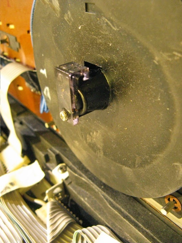
Removing the shaft with the 5 electromagnetic clutches is next. To do this, you only need to remove the 2 small bolts that hold the stop plate.


Then the complete shaft can be taken out for inspection and cleaning. The old belts had been replaced with dial cord as mentioned in an earlier post (click here to go to this post). Be careful: the first clutch comes out completely from the shaft together with a small spring. Easy to loose ! The other clutches can not be removed and are fixed (permanently) to the shaft with a pin.  I like to clean the groves in the clutches where the belt will fit later. These groves can be dirty and result in slipping of the new belts.


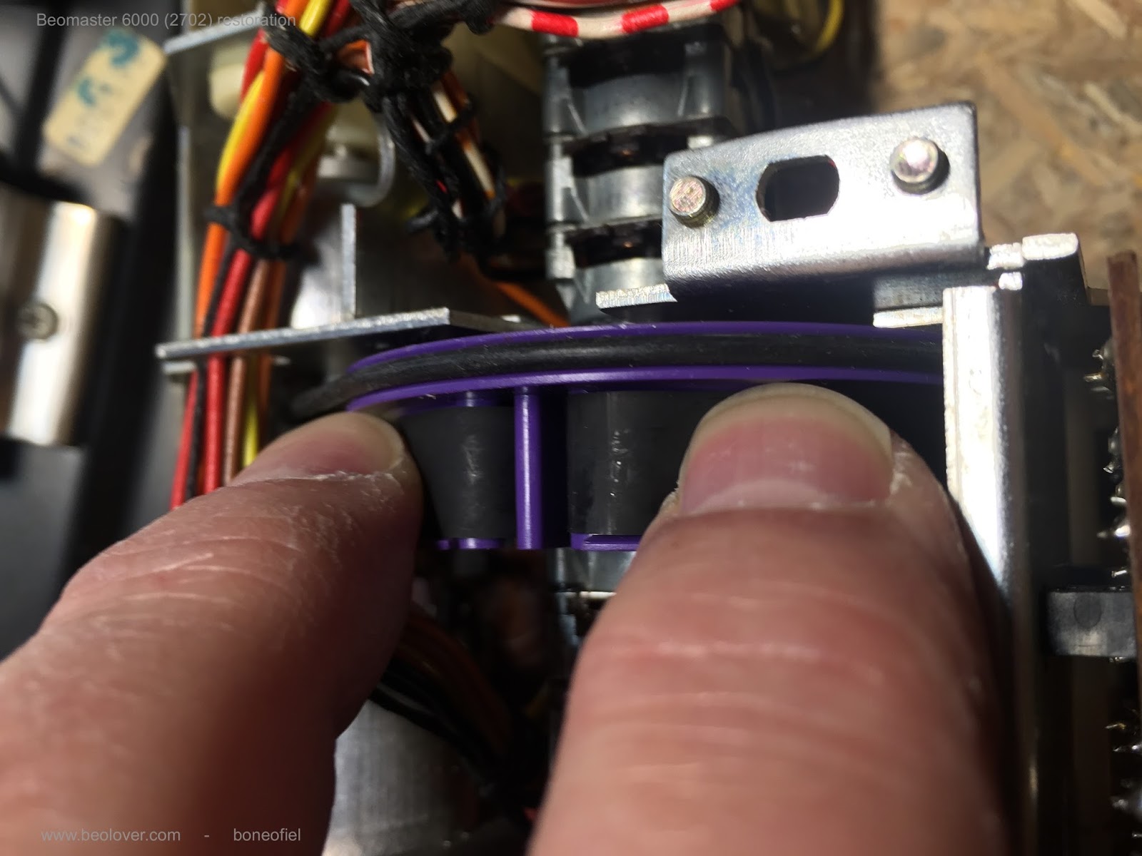
When mounting the shaft back into the frame, the new belts need to be added one by one. Make sure you use the correct material for the belts/O-ring (best is EPDM) and the correct size off course. I use 2mm thick and 54mm inner diameter.


Before putting the shaft back in position it is best to fix the motor with the coupling attached first. Then the shaft can be pushed into the mounted coupling. Don't be surprised that the motor is wobbling a bit. This is the way it was designed !


I also replaced a few tantalum capacitors on the PCB at this time.


Moving on to the display panel. This panel is lit with 6 glass bulbs that illuminate a clean plexiglass plate (with some white bands on it) that is fixed on a shiny mirror like frame. 


After cleaning the frame, I was not all that happy. It still showed some "dirty" places where the mirror finish was a bit corroded. I decided to reapply a layer of silver coating. I used "Silver Plater" from Holland Hallmark. This is a liquid that contains real silver and can be used not only to clean silverware but also adds a tiny layer of silver every time you polish/coat it. I applied 3 layers and got a nice results. The reflection you see in the frame is the window in my room!
Not perfect, but  honestly this plate is just used to reflect light and is not visible from the outside. But...shiny does look nice!


The plexiglass also had some very light damage to some of the white painted bands. I used a permanent marker pen to repair the damage.


The purple wheels got a warm bath to clean them and where fitted back on the potentiometers. 


The 5 potentiometers are now fitted back into the frame together with the recapped tone amplifier PCB.  A thin, flat 10 mm spanner is needed to fix them. Make sure that they fit snugly into the provided cut-out in the frame. It's a good idea to move the wheel a bit outside to fit the spanner. After tightening the nut, push the wheel back in place.


The motor control panel with the display is now almost ready. Remains to fix the indicator bands.


The fragile indicator bands are fixed with wedge type clips onto the purple wheel. While it is not that difficult, it takes some practice to fit them correctly. The B&O service manual shows how to put the band around the different wheels. Study this drawing before starting the installation of the band.


The band should not be to tight, not to slack either. I prefer to put the clips at the back of the panel since there is a bit more room. 


I use two fingers to put some tension on the band and put the plastic clip with my other hand.


OK. That is done !  There is also a  nice video clip made by Beolover on how to replace the belts (click here)


Wednesday, July 22, 2015

Beocord 9000: Exchanging the Rubber Parts in the Tape Mechanism

I made some more progress with the Beocord 9000 that I am restoring right now. I recently received the rubber 'tires' for the idler wheels in the tape drive mechanism and so I set out to install them. The reason I went ahead to do this was that the deck would not rewind properly. At the end of the rewinding process, when the power to the motor is reduced by the microcontroller the winding process became very slow and, depending on the particular tape, it also stopped in some cases. Of course this was not acceptable, so I looked around, and what came up on Beoworld.org suggested that the idler wheel rubber tires can harden over time reducing the friction and hence the transport becomes slow.

It turned out later, after I took the mechanism apart that a previous 'repair' effort on the mechanism bent an important friction pad, which in effect caused the problem. Well, now we have new idler wheel tires in the drive but also a straightened out tab that functions properly again. I think it is part of any decent restoration to refresh the rubber for long term stability, so I do not think the replacement was a useless effort. Anyway, I made a video about the replacement of these idler wheel tires (that can be obtained from Dillen of Beoworld.org...what would we do without him!!...;-). Here is the video (pay attention to the part where I discuss the bent pad - this can happen very easily if the drive is assembled without knowing about this issue):


It is worthwhile pointing out that I had a couple of issues during the rebuilding of the tape drive:

1) The plastic fixture of the clutch had a crack. This seems to be a standard issue with these drives. There are several posts on Beoworld about it and how to fix it with sections of brass pipe. I went a different route, since I did not like that one has to take the clutch apart for fitting the brass segments. My solution was to print a two-part ABS plastic sleeve that I then glued together around the part using Acetone-printer filament slurry. I will make a separate post about this in the near future.

2) After I plugged the drive back into the Beocord, it behaved erratically. When I pressed 'play', for example, it would go on 'fast forward' instead, rewinding ceased to work altogether. It turned out that pulling the plug of the ribbon cable that goes into the microcontroller board caused the board-mounted header to crack several solder points, and that caused intermittent behavior. To I desoldered them, and that fixed everything. This shows the header with the cracks. If you look closely you can see the ring shaped hairline crack around the top pin:


I added some flux and solder to the points and that fixed the problem:


After this I tested the drive, and it performed flawlessly. I measured the fast forward and reverse times for a C90 Maxwell tape:

FFD: 1:44 min with the motor power reduction coming on at about 1:37 min
FRV: 1:40 min; motor power reduction at 1:33 min

The spec from the manual is C60 takes 70 sec in either direction. So I think we are pretty close at ~100 sec for a C90. You guessed it: I do not own C60 tape...never understood their purpose...;-)

What is left to do is to get the rubber pinch roller rebuilt by Terry Witt. While it still performs o.k. it shows a bulging cracked surface, i.e. needs to be fixed to make this a 'full' restoration. Here is a picture:


Wednesday, January 21, 2015

Beomaster 8000: Volume Wheel (Encoder) Damping - 3D Printed Paddle Wheel

This is a follow up to my last blog entry about restoring the damping of the Beomaster 8000 volume wheel rotation. Often, the volume encoder looses all its damping over time, which can create an unpleasant situation when someone uninitiated to the issue accidentally cranks up the volume to 6.0 because the volume wheel does not stop spinning.
My latest solution involves a 3D printed 'paddle wheel' that press-fits on the volume encoder shaft. Together with a more heavy duty high viscosity damping grease, the Nyogel 767A a very smooth purely viscous damping effect can be achieved. I made a short video about the new part and its installation:


Here is a better picture of the part (printed with a Form 1 stereolithography printer):


Saturday, September 27, 2014

Beomaster 8000: Volume Wheel (Encoder) Damping - The Video

I really like my Beomaster 8000 with yesterday's volume wheel damping update! So I decided to implement the same approach in the 8000 that will go to Australia next week. Can't let it go less than perfect!...;-). I used this opportunity to make a short video about the procedure. Enjoy!


Friday, September 26, 2014

Beomaster 8000: Volume Wheel (Encoder) Damping - Better Solution

*********Note: There is an update to this entry where a 3D printed part is used as paddle wheel to increase the interaction with the damping grease*****************************************


I was not really happy with my recent Beomaster 8000 volume encoder damping restoration effort. So I tried a few more things on one of my own 8000s. I realized that the original damping must have been a very heavy damping grease to achieve a sensible damping of the volume wheel. I ordered a sample kit of damping greases from Nye. I tried out their highest viscosity type, 868VH, but this still did not yield a damping as strong as I would have liked it.

After some deliberation, I realized that torque is the issue, and I decided to increase the radius of the encoder shaft for a higher damping force. I found a piece of 3 mm silicone sheet in my stash, and I drilled a 3 mm hole into it, and then cut around it:


The irregular shape results in some added turbulence in the grease. When installed the piece spun freely on the encoder axis, i.e. did not rub significantly on the grease well housing. This ensured a smooth rotation-feel of the encoder, only damped by the viscosity of the grease.

Here are the pics after installing the silicone piece and adding the Nye 868VH damping grease:


I pushed the grease in with a toothpick. Then I installed the cover and wiped the excess grease off:


It is important to adjust the screw properly to hold the wheel in a position flush to the panel surface when it is installed horizontally. Make sure that the wheel does not scrape the housing when turned. The above procedure yielded a damping which reduced spin to about 0.5 rotation when giving it a pretty hard spin. Let's see how this repair fares over time....


Thursday, September 18, 2014

Beomaster 8000: Frequency Dial Not Working

Today one of my friends came over with his Beomaster 8000 in his arms...I restored this one a few years ago, so I felt responsible. The nice bottle of Napa cabernet that came with the Beomaster also helped...;-).

So I put it on the bench and opened it up. A quick test whether the infrared LED in the encoder is toast is by shining a flashlight into the encoder to temporarily 'replace' the LED. The IR receivers in the encoders are somewhat sensitive to white light, i.e. they work with a strong LED flashlight. If the encoder works with the flashlight, the LED is toast (see my entry about fixing these LEDs: http://beolover.blogspot.com/2012/07/beomaster-volume-encoder-repair.html)

In this case the flashlight did not do anything....so I checked the encoder outputs on plug P79. There I got the proper 5V square waves, i.e. the encoder was working.

The next step was to measure the signal at the Schmitt trigger (HEF40196B, 9IC7). The signal arrived there...so on to 9IC3, the master microcontroller. And bingo: no signal at pins 13 and 14. This meant that in both A/B signal paths from the encoder the vias died...

It occurred to me that back then when I fixed this Beomaster up, I did not yet routinely rework the vias on the microprocessor board (PCB #9) when restoring the 8000.
So, I re-soldered all the vias on the board (I assumed the others were probably also close to no-contact...), and everything was fine!

Saturday, September 6, 2014

Beomaster 8000: Volume Wheel (Encoder) Damping

********This is a historic post. Please, Check here for an updated procedure.******************

After the displays were back in the Beomaster 8000, I remembered that the volume encoder wheel had lost all its damping. The picture below shows the backside of the encoder housing (this is actually from another Beomaster, I forgot to take a pic of the assembled feature). Together with the plastic 'clamp' an O-ring seals a compartment where a viscous material can be inserted to dampen the rotation of the encoder. In the case of volume adjustment, this is desired to avoid any accidental 'dial-up' of the volume by the inertia of the fairly heavy metal wheel (think having a party with many happy people interested in your Beomaster...;-).


Geoff at Beoworld.org recently told me that he fixed the damping by putting in some high viscosity grease into the compartment, which worked great. So, I put in Silicone grease (which is the least problematic grease in terms of 'interaction with other materials', i.e. one can expect it to be inert in most settings). Here is a pic:


I also needed to replace the O-Ring. I used a Buna Nitrile 1/2"ID X 5/8"OD X 1/16"CS ring from theoringstore.com, which seemed to have about the dimensions of the old deformed ring.

This procedure resulted in a fairly well damped encoder.

Time to put the Beomaster back together!

Monday, March 17, 2014

Beomaster 6000 Quad: Tuner Pulley Mystery Solved!

Just received a picture from Geoff from his Beomaster 6000 Quad showing the bottom end of the tuning wheel assembly:


He suggested that there is just the external retaining ring missing. I had a closer look at my bearing assembly, and it turned out that the bearing was just jammed at the bottom end of the assembly, rendering it inaccessible for the pulley shaft. His photo encouraged me to push the bearing a bit, and indeed it moved further into the housing. Now the pulley shaft comes through far enough that I could put a clip on it if I had one...


I guess in a couple days I will have an appropriate retaining clip from McMaster.
On to the other issues!

Beomaster 6000 Quad: Tuning Wheel Pulley Damage

Today I removed the bearing that (normally) holds the pulley that is driven by the tuning wheel to have a more diagnostic look. After removing the three screws that hold it to the bottom of the enclosure, it came out. Here are some pics:


And from the bottom:


While it appears that the pulley bottom-end may have been press-fit into the bearing, this cannot be since the pulley groove would be much lower than the the string level in that case. This suggests there is a part missing in between the bearing and the pulley. Not sure at this point what to do about it.