Featured Post

Beolover SyncDrive: DC Platter Motor Replacement for Beogram 4002 and 4004 (Type 551x and 552x)

Late Beogram 4002 and the 4004 (Types 551x and 552x), which have DC platter motors instead of the earlier synchronous AC motors usually suff...

Showing posts with label coupling. Show all posts

Thursday, November 1, 2018

Beomaster 8000: New uProcessor Crystals, Improved Decoupling of the uProcessors, and New IC Sockets

A Beomaster 8000 that I restored in 2014 recently returned to my bench due to some erratic behavior. Apparently it turns itself on spontaneously once in a while. While I was not able to reproduce this behavior for several weeks, I experienced it once with one of my own Beomaster 8000s, and there are some sporadic reports on the internet about similar issues.
Since I was not able to find anything wrong with this Beomaster, I am left with a hypothesis, namely that the uProcessor once in a while suffers from a power fluctuation or that one of the clock crystals is going bad, and that puts it into an unexpected state.
So I decided to replace the crystals and add 100nF decoupling capacitors to the power supply pins of the uProcessor IC, which only carry 1 uF from the factory. These days most of the time one finds 1nF in parallel with 100nF, which allows filtering a broader frequency range.

This shows the inside of the uProcessor can in original condition:
I removed the precious processor ICs from their sockets to ensure that they would not get damaged during the surgery. The crystals and also their capacitors can be charged with a high voltage out of the box, and that can damage the ICs. Therefore, I normally discharge all components against GND and I remove the ICs before working on this board. 
This shows one of the crystal setups in more detail:
I removed the crystal and their two 22pF oscillator capacitors and implanted modern crystals with their specified 18pF capacitors:
I also replaced the IC sockets, while I was in there:
This shows the an original and a new 2 MHz crystal in comparison:
When putting in the new 18pF capacitors, one needs to remember to solder one of the pins from both sides, since it serves as a via.
The final task was to add the 100nF capacitors. This is an easy thing to do since the 1uF cap is soldered between the 5V and GND pins on the back side of the PCB. This shows the original setup for IC3:
I simply soldered the 100uF cap in parallel across the 1uF cap:
After this step I put the board back in, and the Beomaster still worked...let's hope the new parts help suppressing the sudden-on phenomenon. Only the future will show...


Sunday, February 11, 2018

Beomaster 6000 (2702) restoration: Motor control and display panel

After spending some time on an urgent repair for another client, I'm back into the Beomaster 6000 quad project. This time I looked at the motor control unit with the display panel. The main items to check are the motor itself and particularly the coupling with the drive shaft, the magnetic clutches (never seen a broken one), the  5 drive belts (O-ring), indicator bands and clips, glass bulbs and the display panel itself. Let's start...


The motor was taken out, cleaned, the flexible coupling renewed and  fresh silicone grease added. A quick test on my bench power supply revealed a very quiet run and about 15mA of current under no load. 
For the new coupling I used quality clear silicone tube with inner diameter of 3mm and outer of 7mm. This is bit thicker than the original black coupling but gives a nice firm fit.


Removing the shaft with the 5 electromagnetic clutches is next. To do this, you only need to remove the 2 small bolts that hold the stop plate.


Then the complete shaft can be taken out for inspection and cleaning. The old belts had been replaced with dial cord as mentioned in an earlier post (click here to go to this post). Be careful: the first clutch comes out completely from the shaft together with a small spring. Easy to loose ! The other clutches can not be removed and are fixed (permanently) to the shaft with a pin.  I like to clean the groves in the clutches where the belt will fit later. These groves can be dirty and result in slipping of the new belts.


When mounting the shaft back into the frame, the new belts need to be added one by one. Make sure you use the correct material for the belts/O-ring (best is EPDM) and the correct size off course. I use 2mm thick and 54mm inner diameter.


Before putting the shaft back in position it is best to fix the motor with the coupling attached first. Then the shaft can be pushed into the mounted coupling. Don't be surprised that the motor is wobbling a bit. This is the way it was designed !


I also replaced a few tantalum capacitors on the PCB at this time.


Moving on to the display panel. This panel is lit with 6 glass bulbs that illuminate a clean plexiglass plate (with some white bands on it) that is fixed on a shiny mirror like frame. 


After cleaning the frame, I was not all that happy. It still showed some "dirty" places where the mirror finish was a bit corroded. I decided to reapply a layer of silver coating. I used "Silver Plater" from Holland Hallmark. This is a liquid that contains real silver and can be used not only to clean silverware but also adds a tiny layer of silver every time you polish/coat it. I applied 3 layers and got a nice results. The reflection you see in the frame is the window in my room!
Not perfect, but  honestly this plate is just used to reflect light and is not visible from the outside. But...shiny does look nice!


The plexiglass also had some very light damage to some of the white painted bands. I used a permanent marker pen to repair the damage.


The purple wheels got a warm bath to clean them and where fitted back on the potentiometers. 


The 5 potentiometers are now fitted back into the frame together with the recapped tone amplifier PCB.  A thin, flat 10 mm spanner is needed to fix them. Make sure that they fit snugly into the provided cut-out in the frame. It's a good idea to move the wheel a bit outside to fit the spanner. After tightening the nut, push the wheel back in place.


The motor control panel with the display is now almost ready. Remains to fix the indicator bands.


The fragile indicator bands are fixed with wedge type clips onto the purple wheel. While it is not that difficult, it takes some practice to fit them correctly. The B&O service manual shows how to put the band around the different wheels. Study this drawing before starting the installation of the band.


The band should not be to tight, not to slack either. I prefer to put the clips at the back of the panel since there is a bit more room. 


I use two fingers to put some tension on the band and put the plastic clip with my other hand.


OK. That is done !  There is also a  nice video clip made by Beolover on how to replace the belts (click here)


Saturday, March 22, 2014

Beomaster 6000 Quad: Rebuilding the Motor Unit - Some Progress

*********************************************************************************
Note: This entry is 'historic'...it turned out that the Buna-N O-rings mentioned below did not work out. Please, use rings made from EPDM. I used model E70032 from the O-Ring Store (theoringstore.com). The Buna N rings cracked after only one month, and I had to replace them with the EPDM rings. Check out the update on this repair procedure and a detailed repair video at: http://beolover.blogspot.com/2014/05/beomaster-6000-4-channel-rebuilding.html
*********************************************************************************


I received the belts for the motor unit of my Beomaster 6000 Quad from McMaster. They are 'metric Buna-N O-ring, 2mm width, 50mm ID' (9262K208). I measured the broken belts as good as I could, and it seemed these dimensions would fit the bill. The original belts had only 1.8 mm diameter, but 2 mm is all they had.
So I set out to put them in. Not a task for the faint of heart. It is immediately evident that the indicator tapes need to be removed. Sweat started building at the thought. But there is only one way now with this Beomaster: forward!
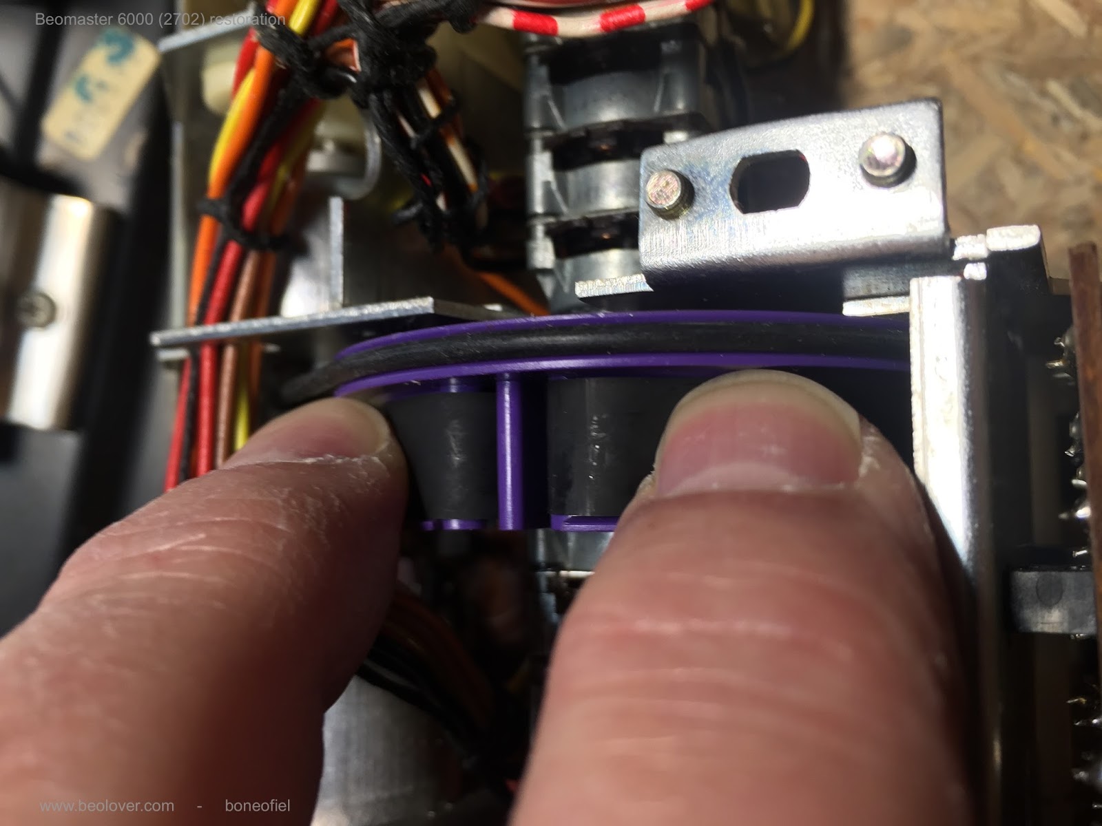
The critical moment is when one takes the V-shaped retaining clips out that clamp the tapes to the purple wheels. Per service manual one is to push them out laterally, which works fairly well (three of them had sort of bonded with the tape/wheel, and it took a bit of force until they started moving). It is best to move the grooves in the wheels a bit away from the display element to obtain a clear path for the clips for moving them out. Here is a pic:


After I removed the five tapes, I went on to get the shaft out. All one has to do there is to remove the plastic bearing at the end of the motor unit and wiggle it out (see below a photo where I put it back in - that should clarify the process). It is a good idea to put a box into the cavity of the motor unit, to lift it out a bit, to create a better working situation.
Here is the shaft after I had it out...a pretty interesting design. The clutches are just metal pieces that are pulled into place by coils (OL1,2,3,5,6 in the schematic).


Then I loosened the potentiometer nuts. Of course my Beomaster 6000 Quad did not come with the appropriate Band and Olufsen supplied special ~1mm thick 10mm wrench. But I am a man of the Dremel, and so I had the 'collet wrench' that came with the set. This wrench has the perfect thickness, but is slightly to small (it may be a 9/32 - not sure). I used the Dremel itself with a grinding tool to widen it up a bit to a 10mm opening:


This fit perfectly:


Note: this pic was taken after the job was done.

All one has to now is to loosen the nuts and wiggle the pot is out. I forgot to take a pic when they were out - the heat of battle...I then put the belts on their groves on the purple wheels. They just stayed snugly put in them by their own tension. Then I put the pots back in and tightened the nuts.

Now came the second hard part: To get the shaft back in while pulling the o-rings into position. I did this in a 'caterpillar' like motion, moving the shaft a bit pulling the o-rings one ager the other on it while moving it a few millimeters forward, moving the rings and so forth. Here is a when I was about halfway through:


And here after putting it all the way through:


After installing the shaft all the way, I tried to turn the wheels by turning the pulleys on the shaft, and everything felt pretty solid and in good contact, while having enough friction to reliably turn the wheels. It seems the belts may do the job.

Now I needed to replace the motor coupling, which was completely rotted away. Here is is before:


And with the new piece of a 3mm ID poly tubing piece:


Since the shaft can only be stuck into the coupling when the motor is installed, I needed to pull the shaft again a bit back, install the motor back into position, and then press the shaft into the coupling. This worked very well:


So far so good. The next step is to put the bands back in. This is probably the biggest problem since the retaining clips have degraded and lost their elasticity. I tried to bend one a bit together to be able to get it into the wheel in a 'dry run' without a tape (not sure what I would do if I damaged them...)
Anyway, this is what happened, as you may guess:


It immediately broke after applying very little force. I guess the others will not be much different. So a solution needs to be found. I have a few ideas, but this needs to 'percolate' a bit more...aside from this damage, a few wires came off of board 12 (motor control) since the board chafed quite a bit on the cardboard box while I was fighting with the shaft and the o-rings. But this is a minor problem. I thought that would happen and I took some nice pics before...Enough for today. More later.