Featured Post

Beolover SyncDrive: DC Platter Motor Replacement for Beogram 4002 and 4004 (Type 551x and 552x)

Late Beogram 4002 and the 4004 (Types 551x and 552x), which have DC platter motors instead of the earlier synchronous AC motors usually suff...

Showing posts with label clutch. Show all posts

Sunday, February 11, 2018

Beomaster 6000 (2702) restoration: Motor control and display panel

After spending some time on an urgent repair for another client, I'm back into the Beomaster 6000 quad project. This time I looked at the motor control unit with the display panel. The main items to check are the motor itself and particularly the coupling with the drive shaft, the magnetic clutches (never seen a broken one), the  5 drive belts (O-ring), indicator bands and clips, glass bulbs and the display panel itself. Let's start...


The motor was taken out, cleaned, the flexible coupling renewed and  fresh silicone grease added. A quick test on my bench power supply revealed a very quiet run and about 15mA of current under no load. 
For the new coupling I used quality clear silicone tube with inner diameter of 3mm and outer of 7mm. This is bit thicker than the original black coupling but gives a nice firm fit.


Removing the shaft with the 5 electromagnetic clutches is next. To do this, you only need to remove the 2 small bolts that hold the stop plate.


Then the complete shaft can be taken out for inspection and cleaning. The old belts had been replaced with dial cord as mentioned in an earlier post (click here to go to this post). Be careful: the first clutch comes out completely from the shaft together with a small spring. Easy to loose ! The other clutches can not be removed and are fixed (permanently) to the shaft with a pin.  I like to clean the groves in the clutches where the belt will fit later. These groves can be dirty and result in slipping of the new belts.


When mounting the shaft back into the frame, the new belts need to be added one by one. Make sure you use the correct material for the belts/O-ring (best is EPDM) and the correct size off course. I use 2mm thick and 54mm inner diameter.


Before putting the shaft back in position it is best to fix the motor with the coupling attached first. Then the shaft can be pushed into the mounted coupling. Don't be surprised that the motor is wobbling a bit. This is the way it was designed !


I also replaced a few tantalum capacitors on the PCB at this time.


Moving on to the display panel. This panel is lit with 6 glass bulbs that illuminate a clean plexiglass plate (with some white bands on it) that is fixed on a shiny mirror like frame. 


After cleaning the frame, I was not all that happy. It still showed some "dirty" places where the mirror finish was a bit corroded. I decided to reapply a layer of silver coating. I used "Silver Plater" from Holland Hallmark. This is a liquid that contains real silver and can be used not only to clean silverware but also adds a tiny layer of silver every time you polish/coat it. I applied 3 layers and got a nice results. The reflection you see in the frame is the window in my room!
Not perfect, but  honestly this plate is just used to reflect light and is not visible from the outside. But...shiny does look nice!


The plexiglass also had some very light damage to some of the white painted bands. I used a permanent marker pen to repair the damage.


The purple wheels got a warm bath to clean them and where fitted back on the potentiometers. 


The 5 potentiometers are now fitted back into the frame together with the recapped tone amplifier PCB.  A thin, flat 10 mm spanner is needed to fix them. Make sure that they fit snugly into the provided cut-out in the frame. It's a good idea to move the wheel a bit outside to fit the spanner. After tightening the nut, push the wheel back in place.


The motor control panel with the display is now almost ready. Remains to fix the indicator bands.


The fragile indicator bands are fixed with wedge type clips onto the purple wheel. While it is not that difficult, it takes some practice to fit them correctly. The B&O service manual shows how to put the band around the different wheels. Study this drawing before starting the installation of the band.


The band should not be to tight, not to slack either. I prefer to put the clips at the back of the panel since there is a bit more room. 


I use two fingers to put some tension on the band and put the plastic clip with my other hand.
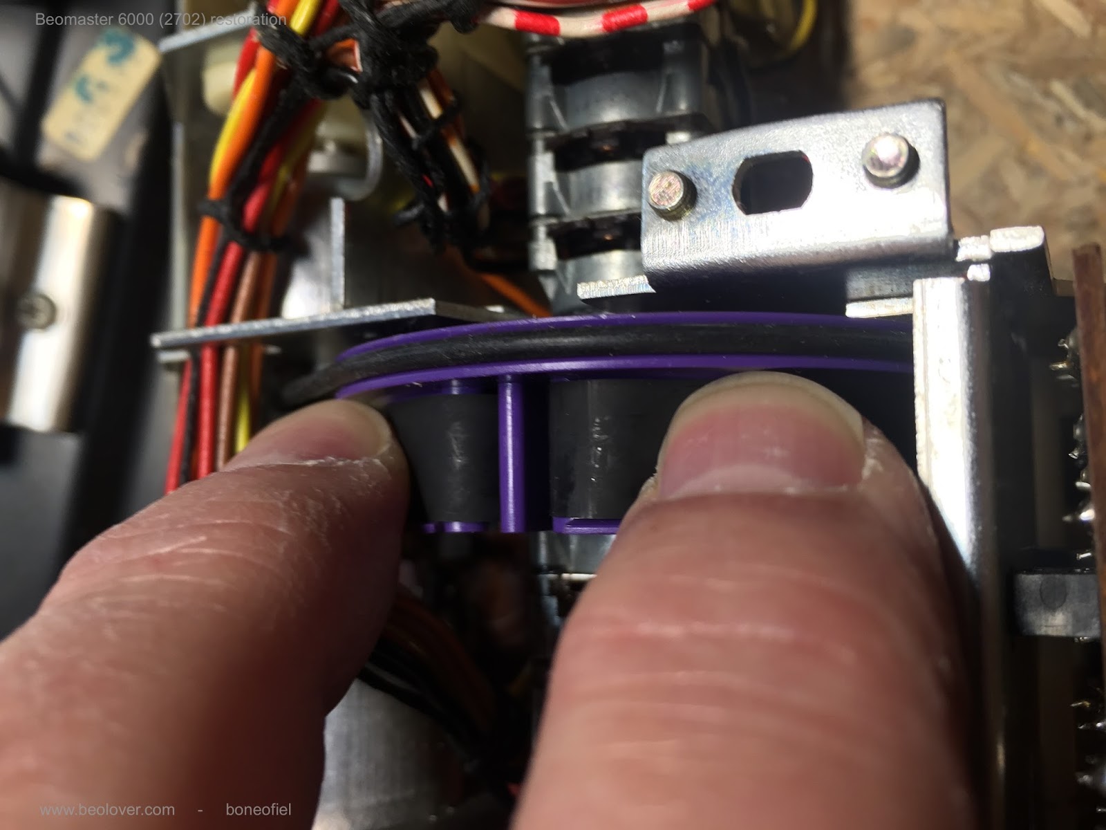


OK. That is done !  There is also a  nice video clip made by Beolover on how to replace the belts (click here)


Saturday, December 24, 2016

Beocord 9000: Identifying Repairs

The disassembly of the tape transport allows me to get to various nooks and crannies for cleaning and locate hard to see places that need repair. This makes sense from a restoration stand point but you pretty much have to disassembly a majority of the transport anyway to replace the rubber wheels.

NOTE: Don't disturb the part of the transport where the tape heads are mounted. Chances are they are still in alignment or, at least very close. There is no need to remove them at this point unless you know they are defective.

Here is a picture that identifies the four rubber wheels that will need to be replaced.


The replacement wheels and the rubber belts I will use are parts I get from Martin Olsen. He has done the research to make sure these replacement parts are accurate reproductions for the Beocord 9000.
Here are the replacement parts for the belts and wheels.


This picture shows the tape heads and the pinch roller (or thrust roller). The picture also shows what type of dust and dirt builds up inside these machines.


One of the rubber wheels to be replaced is part of the Beocord clutch assembly. Every clutch assembly from a Beocord 8000 to 9000 deck I have seen has cracks in the plastic where the pulley shaft mounts (via small brass inserts in the plastic).


I went ahead and disassembled the clutch assembly to apply the fix for the cracked plastic. I cut sections from a brass tube and epoxy into place so the brass sleeves prevent any more damage. The tubing I used is 8.73mm (11/32 inch) x 0.355mm (0.014 inch). I got mine at a hobby store that specializes in parts for remote control airplanes and cars. I used a Dremel tool to cut sections off then file off any burrs. When mounting the brass sleeves I remove the brass mounts the clutch shaft fits in to.


The final repair to identify is the repair of the tape head transport leaf springs. I already know there is one broken spring mount. I need to also check for any other places there are cracked or loose plastic pieces. I found these bad spots by the gears that dampen the cassette holder open/close function.


I will repair those spots with some epoxy when I fix the leaf spring mount here.


I wanted to get the epoxy step done and cured so I could continue with the tape transport. I actually did the cleaning and epoxy step last night so I could continue working today. This picture shows the re-installing of the leaf springs that hold down the tape head transport. Some new TriFlow Red Grease, the 2.5mm ball-bearings and the springs are complete. Next it is on to installing the new wheels and lubricating the moving parts. That should mean the tape transport will be ready to reassemble and test.

Friday, July 24, 2015

Beocord 9000: Repairing a Cracked Clutch Arm

This is a follow up to my initial entry about replacing the idler wheel rubber 'tires' in a Beocord 9000 tape deck. One of the issues I had was that the clutch arm showed a crack where the clutch shaft bearing is press-fitted 


It seems that many of these decks have this issue. A design weakness. While I thought that this is maybe not too dramatic since the strain was released via the crack and the bearing seemed stably in place, I felt that a proper restoration should not leave such a crack unattended. There is an interesting thread on Beoworld.org that was started by Sonavor, who is an expert on these decks. His approach was to buy some fitting copper pipe and cut off small rings that he was able to force over the cracked plastic part. While this is a really pretty looking and solid fix, the disadvantage is that one has to take the clutch apart. I did not want to risk to break the part, so I came up with a different approach:

I designed a 3D printed two-part ABS sleeve that I glued together under pressure using acetone-ABS slurry. This makes a virtually bulk material-strength bond since it dissolves the material at the interface and after evaporation of the solvent an almost uniform piece emerges.

Here is a picture of the parts together with the clutch:
While it was hardening I forced the parts together with a pair of grip pliers

And here is the end result:

I installed this in the Beocord and it works very nicely.