After my recent posts of a Beogram CD50 restoration I opened up and restored two of my own CD50 units. The CD50 in the earlier blog posts was a later model than both of mine. It is serial number 4181953 while mine are 3449007 and 3293019.
My SN:3449007 CD50 was pretty much the same inside as the 4181953 serial number while my 3293019 had quite a few differences under the covers. They all have the same circuitry but the two earlier serial number CD50 units had some factory and/or service center modifications applied.
The purpose of this blog post is to show the typical restoration steps required to get these CD players working again. I will point out some differences between serial numbers in the photos where they show up but the actual restoration tasks are the same on all three CD50 units.
The most common failure on a Beogram CD50 is loading and playing a CD due to the tray mechanism failing. The primary cause of that is a rubber belt that the tray motor powers to move a set of cams and gears. It is the only belt in the Beogram CD50 but nothing can function without it.
That task sounds like a simple and quick change...but it turns out that is not.
Some disassembly of the tray mechanism must be performed to get to the belt. To compound that task even more these CD50 units are at the age where if they still have their original belts, those belts have likely deteriorated into a gooey, sticky mess. The old belt remnants can be in several places and for sure around the pulleys. If that is the case then more disassembly of parts is required to properly clean up the old belt remains.
This post will show that worst case scenario.
The other CD50 restoration task is to replace three capacitors. The CD50 circuits make heavy use of capacitors, including a lot of electrolytic capacitors. We have seen in other vintage audio restorations where a high percentage of those electrolytic capacitors are well out of tolerance after 30 or more years of service. Surprisingly most of the electrolytic capacitors in the CD50 circuits are still in the middle of their tolerance range.
This post will show the three capacitors recommended for replacement.
To start off, here are a couple photos again of a working CD50
The above photos show a CD50 playing through a Beomaster 5000. Also shown is the Master Control Panel 5000 which is the wireless remote control over the Beomaster 5000 which, in turn, has wired remote control over the CD50.
The photo of the CD50 tray out shows that the CD mechanism requires a CD to be inserted with the data side up. That is opposite from most other CD players.
The CD50 loading tray pulls the CD inside where a bottom disc holder pushes the CD up to the laser.
To replace the rubber belt that drives the CD tray loader mechanism some disassembly is required.
The easiest step is removing the CD50 cabinet cover as shown on
this earlier CD50 restoration post.
Once inside all of the fun begins.
The first step is to get the CD50 Laser Assembly out of the way.
There are a number of different ways to start the disassembly but I have settled in to removing the front left holding bracket first.
Once one of the rubber padded brackets is removed there are four Laser Module assembly screws that secure it to rubber padded bases. Remove those four screws and the Laser Module assembly can be lifted out of the way.
I place a couple of rubber insulating mats over the PCB 7 board and lay the Laser Module assembly on top. This way I haven't disconnected any cables and the CD50 can still be turned on and operated to check the CD tray mechanism.
It isn't necessary but I also like unbolting the voltage selection bracket and CD50 power transformer, then place them out of the way on the rubber mat next to the Laser Module assembly. It just gives me more room to operate on the CD tray mechanism.
Here is the CD tray mechanism now that the Laser Module assembly is moved out of the way.
The CD tray is closed in this photo.
The top Cam-wheel in the photo controls the S301 and S303 electric switches that tell the CD50 control circuit what the status of the CD is (Tray open, Tray closed, CD clamped).
The next photo shows the position of the Cam-wheel and S301 switch when a CD is clamped.
Note that the lower disc holder is raised where it would be pressing a CD up against the top disc holder.
Also note the screw holding the Cam-wheel in place versus the larger nut that holds the Cam-wheel in place in the earlier photos. The photo below is from an early serial number CD50. B&O changed that Cam-wheel mount in later serial numbers.
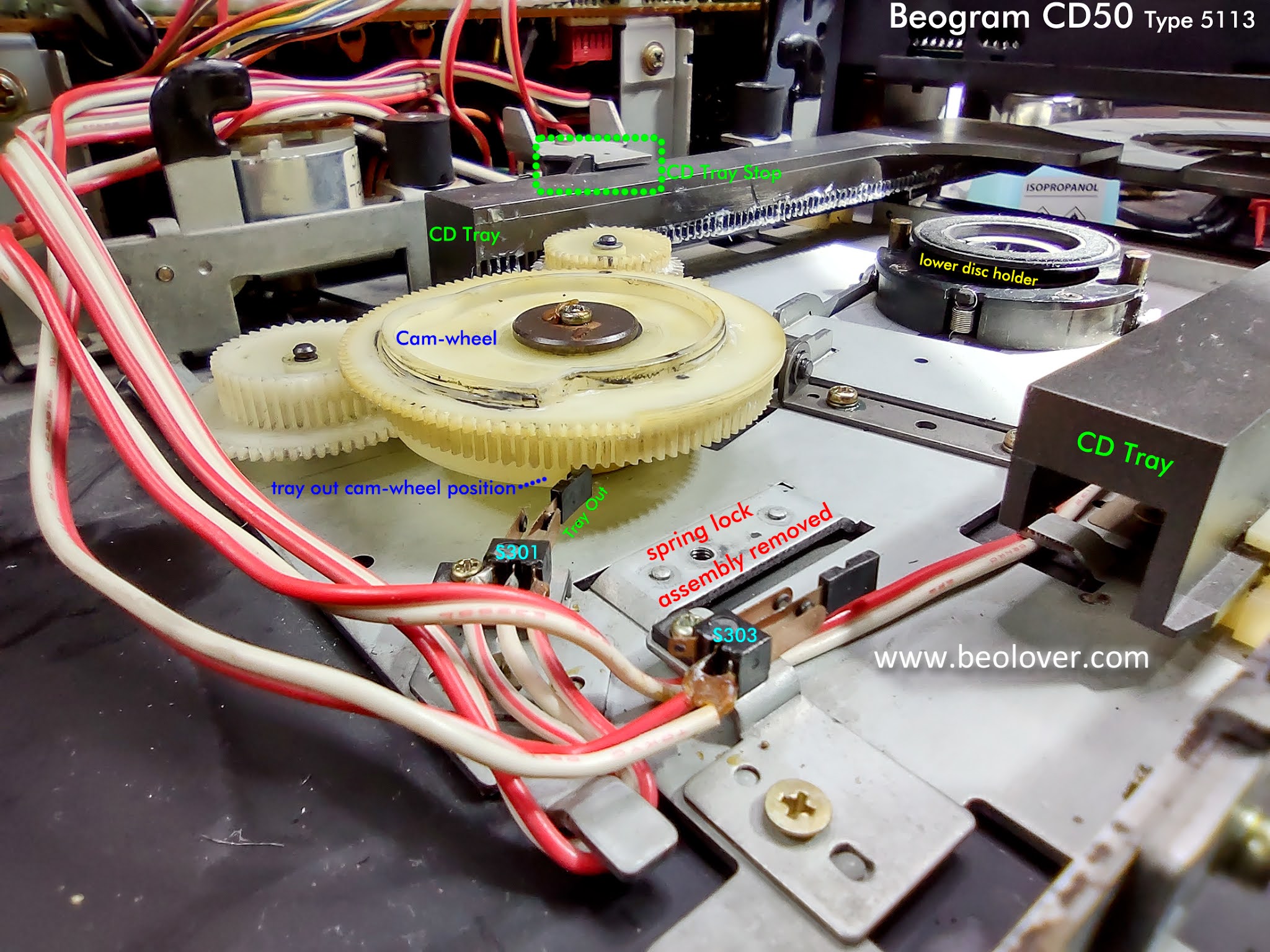
The next photo shows the Cam-wheel and other CD tray components when the CD tray is in the out position.
To better show the Cam-wheel component and to prepare for further disassembly to get to the CD tray belt, I removed the spring lock assembly for the next photo.
To get to the CD tray belt you have to remove the Cam-wheel. That means removing the retaining nut from the Cam-wheel.
In the next photo I have removed the CD tray metal stop and taken the plastic CD tray out. It is not necessary to remove the plastic tray but I occasionally do for more working room. That is especially true if there is old rubber belt residue to clean up...as will be shown further down in this post.
When lifting off the Cam-wheel you will see that there are actually two Cam-wheel components. The top Cam-wheel which rotates and causes the various CD loading steps to occur...and the lower (smaller) Cam-wheel component which operates the lifting and lowering of the lower disc holder.

NOTE: When removing the gear components to get to the belt replacement it is common practice to use a marking pen to mark the position of the gear relationships. I initially did that but my feeling now is that is not necessary. It is much better to learn what the proper position of the Cam-wheel components and CD tray switches should be in for the various CD tray positions. Learning that allows me to reassemble the gears and Cam-wheel components without the need for other guide marks.
Here is the top Cam-wheel removed.
Next comes the Gear-wheel that works with the pulley.
If you reach this step and the rubber belt is like the one pictured below or simply broken then the replacement task is simply to remove the old belt and attach a new one.
However....if you discover the old belt has deteriorated like this photo (from a later model CD50)
....then you have a bunch of belt residue cleanup ahead of you. That will probably require some more disassembly in order to get the CD tray motor out as its pulley will have the gooey belt residue as well.
The next few photos show before and after pictures of the belt residue cleanup.
In either case, with the extra cleanup step or not, the result should be a nice new belt installed.
Now begins the reassembly.
The notations on the photos are important. Begin the reassembly with the CD tray at the full open stop.
It is important that the retaining screw/washer/nut on the top Cam-wheel is not tight against the Cam-wheel.
The job of the retaining screw/washer/nut is to keep the Cam-wheel from coming off. The Cam-wheel must be able to easily be turned by the tray gears.
Here is the CD50 tray mechanism in the tray closed position but with the lower CD clamp mechanism in its lowered position.
Here is the CD50 tray mechanism advanced to the CD clamping position (the position it will be in when playing a CD).
The CD50 Laser Module assembly can now be returned to its position over the CD tray assembly and the restoration tasks can move over to the capacitors on the CD50 circuit boards.
Here is a photo of the CD50 with the main boards identified.
Two of the three capacitors that I replace are on PCB 1 (Display & Key Control Board).
However, the main AC from the CD50 power cord enters the CD50 on this board on route to the transformer. That being the case there is a 10nF X2 safety capacitor (1C28) on PCB 1. At over 35 years of age the 1C28 capacitor is due for replacement.
PCB 1 also has a 100uF, 25V electrolytic capacitor (1C1) that is for the +5V power on the display board. When checking all of the electrolytic capacitors on the three CD50 units I recently worked on, all three 1C1 capacitors measured around 45uF instead of their rated 100uF. Quite a ways out of tolerance.
The third capacitor I replace is on PCB 8 (Decoder, System Control Board). The capacitor there is 8C352. A 33uF, 25V electrolytic capacitor. Only one of the three CD50 units had a failed 8C352 capacitor. It measured 30nF rather than 33uF. The bad capacitor also prevented the CD50 audio muting circuit from functioning. That makes sense as the audio muting circuit is what 8C352 is a part of.
I checked with other CD50 restorers and it turns out 8C352 has caused problems for other owners too.
As a precautionary measure I went ahead and replaced 8C352 on all three CD50 units I worked on.
Here is a photo of the two capacitors on PCB 1.
Before:
After:
Here is the 8C352 33uF capacitor on PCB 8
Before:
After:
Naturally it is possible for serious CD failures such as the Laser Module but for a typical, well taken care of Beogram CD50 that is just a victim of old age, the tasks listed here will usually get the unit back in good working order.