Featured Post

Beogram Commander Remote Control: Maybe This is the Final Version!..;-)

This is a follow up to my recent post about the redesigned Beogram Commander remote control board, which now works in both (DC-motor) Beogr...

Wednesday, April 29, 2015

Beogram 4000: Replacing the Reservoir and Motor Capacitors Using a 3D Printed Adapter

Today I received the 3D printed adapter for the new reservoir and motor capacitors of the Beogram 4000 that I am currently rebuilding. Modern capacitors are considerably smaller than the original  1970s types, so a 3D printed adapter makes for a clean implementation with no wiggly or loose parts. 

Here are a couple impressions of the assembly with the new caps:


I replaced the original 150uF unipolar motor capacitor with two axial 300uF types back to back. The other capacitors are Rubycon, Panasonic and Multicomp 105C types for a long lasting setup. 

********Update: See here for a detailed view of how to prepare the replacement capacitor assembly before soldering the wires to it***********

This is the first time that I work on a 4000, hence, before I took the original setup apart, I made a detailed schematic of the wiring for the record in case there is confusion at some point during the operation. Mixing up some of the wires could potentially cause considerable havoc:

Then I unsoldered everything and put in the new capacitor assemblies:


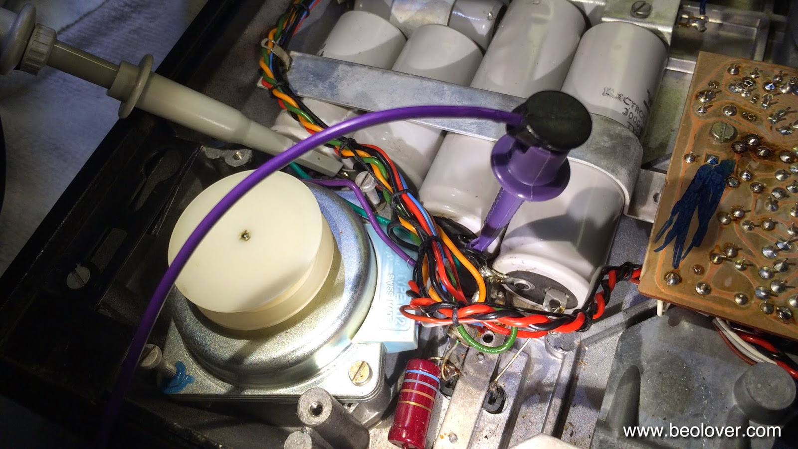
Here is a detail shot of the classic Zener diode-based 24V emitter follower regulator setup. The regulating transistor is directly bolted (via an insulation pad) to the cabinet metal bottom for heat dissipation. The metal bar across the setup also serves as collector terminal. The Zener diode is the short can that is soldered between the current limiting resistor/transistor base node and the negative ends of the 3300uF reservoir caps that serve as system ground:
After a thorough double check of all connections, I plugged the Beogram in, and started it up. Everything seems happy! This is Beolove!


Monday, April 27, 2015

Beogram 4000: Adjusting the AC Motor Voltage

When I initially tested the Beogram 4000 that I am currently restoring, I noticed that the motor was running a bit noisy, especially at 45 RPM. After I replaced all the electrolytic capacitors, this got better, but did not go fully away. So it was time to look into the motor voltage and the waveform that is presented to it by the Wien bridge oscillator (a nice classic design including the amplitude control light bulb that acts as a variable resistor that increases its resistance as the current increases - pretty nifty!). The AC waveform amplitude can be measured at one of the motor leads relative to GND.

This shows how I hooked up the oscilloscope probe between the 150uF unipolar phase shift capacitor for the 2nd phase of the motor and the 4000uF coupling capacitor to the motor drive amplifier (the purple clip makes the GND connection conveniently using the negative pads of the 3000uF reservoir caps):

The GND connection was made at the negative ends of the 3000uF reservoir caps. This is what I found at 33 RPM:


The RMS voltage was at 7.9V and the signal was clipped. A clear case of overdriving. 45 RPM looked like this: 

Per service manual, the drive is to be adjusted to a RMS voltage of 6.5V at 33 RPM. I switched back to 33 RPM and turned the MOT potentiometer on the main circuit board until I saw a perfect waveform at 6.5V:


I also adjusted the "33" RPM trimmer (to the right of the MOT trimmer) until I got the specced frequency of 42.3 Hz.

An issue of this design is that 45 and 33 RPM have the same MOT trimmer setting but the oscillator puts out different amplitudes. Hence there is a small difference in the drive amplitude at 45 when the adjustment is made at 33:


There is also a small amount of distortion. This can easily be reduced if the drive voltage is reduced a bit to 5.5V:

But of course this results in a too low 33 RPM voltage of only 5.8V RMS at this setting:

I guess the designers elected to live with this small imperfection, since 45 is not so important historically. It also should be noted that the motor runs now very quietly at 45 despite the slight distortion and too low voltage. In light of the new 45 RPM audiophile vinyls, of course, one might consider getting a second 4000 adjusted perfectly for 45 RMP...;-). 


Sunday, April 26, 2015

Beogram 4000: Recapping the PCBs

Today, I exchanged all the electrolytic capacitors on the PCBs of the Beogram 4000 that I am restoring right now. I definitely recommend doing this at this age, since the tantalum capacitors can fail in fiery way when they short circuit. I only use longer lasting 105C types from major Japanese manufacturers. I started out by exchanging the two red tantalum caps on the power supply board. I realized that one of the two screws that holds the board in place is missing, and that the other screw was only barely tight. This could have easily produced an interesting short circuit. I guess I was lucky:
This picture shows the board after replacing the caps, and adding a stainless M3 screw:


On to the main board. There is one added capacitor on the conductor side between the emitter and the base of 1TR22:

After replacement:
The main board also lacked a screw, but since there are four in total, it still was held in place securely. I removed the screws and turned it around. Here is a picture of the original condition. No visible damages to the orange electrolytics (this type often fails at this age, and often one can find them with cracks or leaking):
This picture shows the board after replacing them:

And a detail shot:


Thursday, April 23, 2015

Beomaster 8000: Replacement of the Speaker Switches

The final step of my current Beomaster 8000 restoration was to replace the original speaker switches with new encapsulated ones. Due to the encapsulated construction the new speakers do not have the PCB style base plate that is used in the Beomaster to align them with the small compartments that holds the speaker switches in place. I recently designed some laser cut adapter plates that fit the new switches. More information about this procedure can be found in this blog entry.

Here are a few pictures of this procedure:
This shows the original switches removed from their compartments and turned around:

New switches and adapter plates installed:
And new switches installed in their compartments with the heat sink cover back on:

This concludes the restoration of this Beomaster! Now I will test it for a while in my Beosystem 8000 to make sure there are no loose ends.


Wednesday, April 22, 2015

Beogram 4000: Cleaning of the Tone Arm Carriage Position Switches and a Non-Returning Carriage

Before doing my standard rebuilding steps on the Beogram 4000 that I am currently restoring I decided to make sure the control system works properly. Earlier tests revealed that the arm carriage would not return to the home position if set loose across the platter when no record was present. Essentially, the carriage would run all the way to the center of the record and then stop. If everything is o.k. it should trigger the End Switch (ES) and then return to the home position all the way to the right and turn the turntable off.

I decided to start tackling this issue by making sure the carriage position switches work properly. I think it is generally a good idea to give these switches some attention, since they are vital for the trouble free operation of this model. It is not too difficult to do, but I thought a video might prove helpful for other enthusiasts when they engage with this beautiful design. So, here we go:


After I was done with cleaning the switches, I tried the carriage run again. And it still did not work! Closer inspection revealed that the spring that activates the ES switch did not fully engage the switch. I removed the spring carrier a second time, and bent this particular spring a bit downwards to give the switch a bit more travel. This fixed the problem, and the carriage now returned if set loose across an empty platter.

However further play with the mechanism revealed that it was still possible to accidentally drive the carriage into an end position where the ES would not be triggered. This condition occurred when using the left-arrow on the keypad to drive the carriage beyond the point where the ES is activated (the arrow key apparently overrides the ES). In this situation the ES released again, and that prevented the carriage from returning after letting the arrow-key go.

This issue was solved by moving the spring that activates the ES a bit to the right on the carrier plate. In effect, this allows to drive the carriage to its physical end point with the arrow key, while not exceeding the turn on zone of the ES switch.


Monday, April 20, 2015

Beogram 4000: First Contact

A happy day in Beolover's life!! A Beogram 4000 (5215) arrived for some TLC! I always wanted one, but of course here in the US they are hard to come by. The next best thing to owning is to work on one! I was always fascinated by their diode-transistor-logic (DTL) control system built from some early NAND/NOR gates and diode arrays. I took it out of the box and set it up for a test drive. I was told that it is 'mechanically rebuilt' and that it mostly works. I removed the aluminum panels and here is how it looks like (yes, I know...the cabinet is painted over black!...I hope whoever did this will roast a long time in vintage-hifi purgatory for this...;-):


I really like the square keypad made from brushed aluminum instead of the fragile paint coated keys of the later models. Aside from the black cabinet, the hood also has some issues and needs to get polished:


Almost looks like someone used some solvents on the front and accidentally dissolved the surface layer of the plexiglass...nothing that could not be cured with MicroMesh and some elbow grease...

Other interesting features of the 4000 are the very cool strobe light with integrated mirror that allows to check on the strobe pattern that is on the bottom side of the platter:


The strobe set-up can be shifted to either bring the 50 or 60 Hz patterns into the field of vision through the square window in the panel to the right. A great vintage feature!

Also intriguing is the 'position indicator' that assigns a numerical value to the position of the stylus on the record:


The red plastic part is pushed along with the carriage. The lower end serves as a scale indicator on a backlit scale (the light bulb seems to be out in this unit) above the keypad. A nice pre-digital way to find a certain location in a recording...those were the days!

Another interesting detail is the potentiometer that allows the control of the intensity of the tracking sensor light bulb. This allows the adjustment of the gain of the mechanism:


And here is a shot of the power supply PCB, where reed relays (yellow) are used to switch the power rails:


After admiring this awesome design, I switched it to 110V and plugged it in. I pressed 'ON' and the carriage advanced. Not finding a record it went all the way across the platter as it should and then, well, it got stuck at the end...Only pressing "OFF" returned it to the home position...My guess is that the end switch (ES) may be corroded...After that I put on a record and played it. Everything went well, and the return mechanism at the end of the record worked, too. However, I noticed some high pitched interference in the speakers while it played...not sure yet what may cause this. We will see...it is still early in the 'process'.
For now I am enjoying the circuit diagram a bit...Luckily, the data sheets for the DTL ICs are readily available from the usual sources. Great bedtime reading! This is Beolove!...;-)


Beomaster 8000: Display Repair (III) - Rebuilt Displays Installed on PCB, LED Replacements for the Indicator Lights, and a Broken Transistor

Another 24hrs test of the rebuilt Beomaster 8000 displays passed without incident. So it was finally time to put the displays back on the board and test them in the Beomaster. I also replaced the indicator light bulbs with my latest SMD LED replacement boards. Here is a picture of the boards. They fit directly into the indicator cabinets as a drop-in replacement for the light bulbs:


Some more detail about these boards is given in an earlier blog entry, and a YouTube video.

This photo shows the full glory of the display PCB after everything was put together. The covers of the indicators are off, to show the LEDs:

And here with the red covers on:

There was a bit of an excitement during this effort, since at first the 'clipping' indicator would not work properly after I replaced the light bulb with my LED assemblies. What happened was that the LEDs would not go off if there was no clipping. In effect the LEDs behaved as if I had not removed the collector resistor (R40) from IC4, but I had. So something was fundamentally wrong. The plot thickened when I measured the base voltage at IC4 when clipping was on: I only got 0.6V, while it should be 1.2V since IC4 is a Darlington transistor where two diode drops occur between base and emitter. IC4 is right above the clipping indicator cabinet:


This suggested that one of the transistors in the Darlington had a significant problem. The next test was to connect the base of IC4 to ground. If the transistor is o.k. the LEDs should have gone off, but they only reduced their intensity somewhat. All this suggested that IC4 was damaged. I replaced it, and then everything was fine. 

This leaves replacing the speaker switches in this Beomaster, and then this restoration will be complete.


Sunday, April 19, 2015

Beomaster 8000: Display Repair (II) - Assembly and Test

After a 24 hrs 'burn in' in my test fixture, I reassembled the Beomaster 8000 displays using my latest method to fix the red covers back to the PCBs. I now really like using hot glue for that. It can still be removed without much of a trace if one ever needs to get back in there, while making a pretty strong bond. And from the outside of the Beomaster the glue is not visible due to the bezel underneath the glass panel:

I usually run them for another night after glueing them back together, just to make sure that all than handling did not cause any trouble with the solder bonds of the LEDs:


Tomorrow, I will put them back on the PCB and also replace the incandescent light bulbs of the indicator lights with LED assemblies.


Saturday, April 18, 2015

Beomaster 8000: Display Repair (I) - Intermittent Display Segments Replaced with SMD LEDs

The Beomaster 8000 that had the flipped Tape inputs, also had some intermittent display segments. It seems there are two stages of display death. First the segments go intermittent. Often they still work once the Beomaster has heated up, but they blink once in a while...not very pretty. So we decided to rebuild the displays with SMD LEDs. First I took the display PCB out:

Then I unsoldered the displays and removed them. It is best to do all at once. That makes it much more straight forward to take them out from the board:


Then I opened them up:

Here is a picture of the frequency display with the original LEDs still on there. They are not encapsulated, and this is the problem. The small bonding wires detach over time, and that causes the blinking and final disconnect of the LEDs. 
This shows the same board after replacing the LEDs with SMD packages:

I did this to all four displays. Now they are running for 24 hrs in my test fixture to make sure that everything is stable:

Tomorrow, I will put them back together and then test them for some more time before putting them back into the Beomaster.


Beomaster 8000: 3D Printed Control Panel Lid Damper Arm

This is a follow up to an earlier post, where I encountered a cracked control panel lid damper arm. In the meantime I was able to replace the broken part with a 3D printed replacement. I made a short video about this process:


Here are a few high res pictures:

The broken arm:

The 3D printed replacement installed. It was printed on a Stratasys uPrint to achieve the necessary precision. It needs to fit snugly on the damper shaft, and the 'hook' that connects to the linkage needs to have the correct diameter to prevent disconnection of the linkage:

and inside the Beomaster:


Thursday, April 16, 2015

Beomaster 8000: uProcessor Board - Jumpers/Resoldering Vias and Two New Capacitors

The Beomaster 8000 display board that I just restored came with the uProcessor PCB attached. So I checked on the B&O recommended jumpers that bridge the bunch of vias that often go intermittent on these boards. Here is the view from the top after removing the EMI cans:

And from the bottom. It appears that the jumpers were put into place already during an earlier visit to a service department:

I reflowed the vias that they did not cover, and then replaced the two electrolytic capacitors on the board:

After this I replaced the can covers and then cleaned all headers with a fiber glass pen. A thin DeoxIT D100L coat on the header pins finished the job.


Beomaster 8000: Replacing the Incandescent Indicator Light Bulbs with SMD LEDs

It was decided to also replace the incandescent indicator light bulbs of the Beomaster 8000 display board that I recently received for rebuilding. I think that was a great idea, since these light bulbs are notorious for breaking during shipping - they often have brittle leads that break off right at the point where they enter the glass bulbs.

For some time I wondered how to improve the process that I developed last year. So far, I replaced the bulbs in all my 8000 restorations with two through hole-style LEDs in series with a resistor. While this worked great, I thought this could be improved by the design of small circuit boards that hold three surface mount LEDs with their resistors. So I took this opportunity to go for it! I made a short video about the process (in a sense this is an update to my earlier video):


Here are a few pictures:

The assembled PCBs. Every PCB has three LEDs in parallel:

Installed in comparison with an original light bulb (the bulb is a bit too red tinged - I think the camera was confused by the LEDs...):

With red covers on. The LEDs yield a very similar appearance as the original light bulbs:

This picture shows the appearance after replacing all four bulbs:

After this was done I also replaced the two electrolytic capacitors on this board to complete the job. Now everything is beolovely in display-land! Time to ship this board back to its Beomaster 8000!