Featured Post

Beolover SyncDrive: DC Platter Motor Replacement for Beogram 4002 and 4004 (Type 551x and 552x)

Late Beogram 4002 and the 4004 (Types 551x and 552x), which have DC platter motors instead of the earlier synchronous AC motors usually suff...

Showing posts with label carriage. Show all posts

Saturday, July 18, 2026

Beogram 4004 (5526): Upgrade With a New Beolover Carriage Motor and the Commander Remote Control System

I just sold a fully restored Beogram 4004 (Type 5526) that I offered via my store to a customer in California. Read here about the work done on this unit. My customer decided to get the unit upgraded with a new Beolover carriage motor and the Commander remote control.

The new carriage motors run much quieter than the original ones, and the Commander allows full control of all functions with an Apple remote. The Commander also adds auto-repeat functionality.

I put it on the bench and removed the aluminum panels. This shows the original motor still in place:

I extracted the motor, opened up the enclosure, and inserted the new Beolover carriage motor:
This shows the new motor installed:

Then I removed the keypad assembly to install the Commander remote control. Since this was a 4004, the Commander gets its power from the output PCB that is located under the keypad:
I plugged the Commander board into the keypad header on the main board and put the power breakout adapter into the keypad header on the output board. Then I connected the Commander with the white harness to the small jack on the breakout adapter: 
Here a detail shot of the power connection:
Then I plugged the keypad back in and bolted the autorepeat indicator in place with the main keypad mounting screw:
This concluded my work on the upgrades. Now I will play this Beogram a bit, and then it will be time to send it to its new owner.


Thursday, July 2, 2026

Beogram 8002: Skipping and Jerky Run-Off Carriage Motion - Installation and Test of a New Beolover Carriage Motor

It is good that I always listen to a restored Beogram for a while before I send it out. Some issues can only be detected after a longer period of use since they are intermittent or subtle. This also applied to the Beogram 8002 (Type 5633) that I recently sold to a customer in the UK. While I played it, I realized that the pickup occasionally skipped on records that I knew were perfectly fine. This only happened on a few sides that I played. But it indicated that something was wrong.

I encountered a similar issue a while back, where I resorted to tweaking the H-bridge gain to give the motor a bit more power. The reason for such behavior is increasing friction in the motor or elsewhere in the carriage mechanism, causing 'sticktion' where the motor does not get enough power to overcome static friction, while the arm moves inward on the record. After a few more turns of the record, the tracking sensor is finally at a point where the voltage at the carriage motor is high enough to overcome the stuck mechanism, and the motor suddenly starts running at a high speed so the carriage can catch up with the arm. This rapid catching-up process can cause sufficient mechanical turbulence that the very light tonearm skips a groove.

In this case, there was yet another indication that the motor had an issue: During runoff, the carriage moved in a few big jerky steps instead of a smooth, quick motion tracking the needle as the runoff groove drags it towards the center of the record until auto-return is triggered.

This time I thought, why not see if one can replace the Beogram 8002/8000 carriage motors with the Beolover Carriage Motor for Beogram 4000, 4002, and 4004. A quick measurement on the motor terminals indicated that the motors in the 8002 run at similar voltages to the motors in the 400x.

This shows the open carriage motor compartment of the 8002:

First, I unsoldered the brown lead and connected my multimeter in current measurement mode between the wire and the motor terminal. Then I operated the turntable to see what the maximum current might be that this motor draws:
As expected, the motor draws the most current (~70 mA) during the carriage return after pressing STOP.
I removed the motor:
This shows the original motor in comparison to the Beolover motor:
The new motor is a bit smaller. Like most new designs, it is more efficient than the original motors due to better magnets and better manufacturing techniques available today.
Due to the size difference, I had to design an adapter to make the new motor fit into the original motor housing. This is what I came up with:
I 3D-printed two plastic clam shells to increase the diameter and length of the motor to match the original form factor. The additional two EPDM rubber rings serve as vibration insulation. They are put on the motor like this:
Then the plastic pieces are fitted around the motor:
The plastic pieces have two protrusions that hold the motor in place and prevent it from sliding inside the housing:
The new motors have a small round mark next to one of the terminals. The brown wire needs to be connected where the mark is, and the blue one goes to the other terminal.
I soldered the blue wire:
Then I did another current measurement between the brown wire end and the unconnected motor terminal:
Like the original motor, this motor drew the largest current during carriage return. At 50 mA, it is about 30% smaller than the value of the original motor. This was to be expected. In the Beogram 400x series of turntables, I saw a similar power reduction for the same performance. Some things get better as time marches on!...;-). Lower power is always preferable. It reduces the stress on the H-bridge components and also results in a quieter and lower vibration operation. After this test, I connected the brown wire. Since it is shorter, I had to put in a wire bridge to extend it to the motor terminal:
The cover still fits perfectly:
This is how it looks from the front:
After this installation, I listened to a few records with the new motor, and everything worked very nicely. I noticed how much more quietly the motor operated during <</>> and START and STOP operations. Significantly fewer vibrations compared to the original motor! Beolovely!

At that point, I realized that it would be nice to get some oscilloscope shots of the tracking signal on the motor terminals. So I opened the motor housing again and connected my oscilloscope between the motor terminals. This trace gives a nice summary of the motor operation. It essentially captures the voltage fluctuations during the last few turns of the record before the 'run off' groove, then the signal during run off until auto-return is triggered, followed by the actual return:
I wanted to compare this signal with the original motor, and so I installed the original motor for another measurement. This shows the same operational sequence as above:
While the overall pattern looks similar, there are notable differences: The voltage jumps during regular tracking are larger for the original motor. They also have a higher baseline. This indicates that the tracking sensor needs to send more voltage before the motor moves. Secondly, the run-off signal confirms what I observed visually, that the carriage makes bigger jumps. Comparison to the new motor shows that the original motor moves in 3-4 big steps, while the new motor gets a much larger number of voltage pulses, causing it to move the carriage much more smoothly.

In summary, I think the Beolover carriage motor is an excellent substitute for the original motors, which seem to be on the verge to develop age related issues. If you are interested in upgrading your Beogram 8002 or 8000 with a new carriage motor, it is now available via the Beolover's DKaudiolover store!


Sunday, April 26, 2026

Beogram 4002 (5503): New Monolithic Beolover Carriage Position Sensor for AC-Motor Beogram 4002 (Types 550x)

A little more than a year ago I designed a replacement part for the carriage position sensor PCB in DC platter motor Beogram 4002 and 4004 (Types 551x and 552x). This board takes the guesswork out when the carriage position sensor does not work properly. The original design is fairly sensitive to the alignment between the IR diode and the photoresistor, as well as the alignment of the ruler relative ot the sensor, and it can be tedious to get everything properly adjusted.

The Beolover Carriage Position PCB for Beogram 4002 and 4004 (Types 551x/552x) is based on a modern monolithic IR photo-interrupter and circuitry that generates a clean and precise digital output signal for driving 1TR17 on the main PCB.

Sadly, this solution only works in the later DC motor Beograms. The earlier Beogram 4002 with AC platter motor has a much more complicated hard-wired carriage position sensor PCB that is not very easily replaced. But when I recently restored an AC motor Type 5503 Beogram 4002, and it gave me grief with detecting the runout groove reliably, I thought it would be nice to have a solution for these models, too!

Since replacing the entire board is complicated and unnecessary, I designed a replacement for just the sensor part of the board. I designed a board that simply piggybacks onto the main PCB, replacing only the original sensor bulb and photoresistor. This board adapts the same reliable circuit that I used on the DC motor PCB. 

This shows the final version of the Beolover Carriage Position Sensor for Beogram 4002 (Types 550x):


Let's see how it is installed:

This shows the original setup. The photoresistor is in the black housing in front of the 'plexiglass ruler' bolted to the carriage assembly:


After removing the two screws that hold the ruler assembly in place, it can be removed. This reveals the black bulb housing under the ruler.
Here is a view from a different angle (I already had the orange capacitor and white solenoid resistor replaced when I took this photo):
After removal of the bulb cover, the bulb is visible:
The first step for the installation of the new Beolover Carriage Position Sensor for Beogram 4002 (Types 550x) is removing both the photoresistor and the bulb and cleaning the five solder pads indicated below of all solder:
This is best done with a desolder gun since the pads need to be clean and flat so that the Beolover board can be placed onto the original board surface. The board needs to be aligned as shown in the picture below:
This shows it aligned and soldered in place:
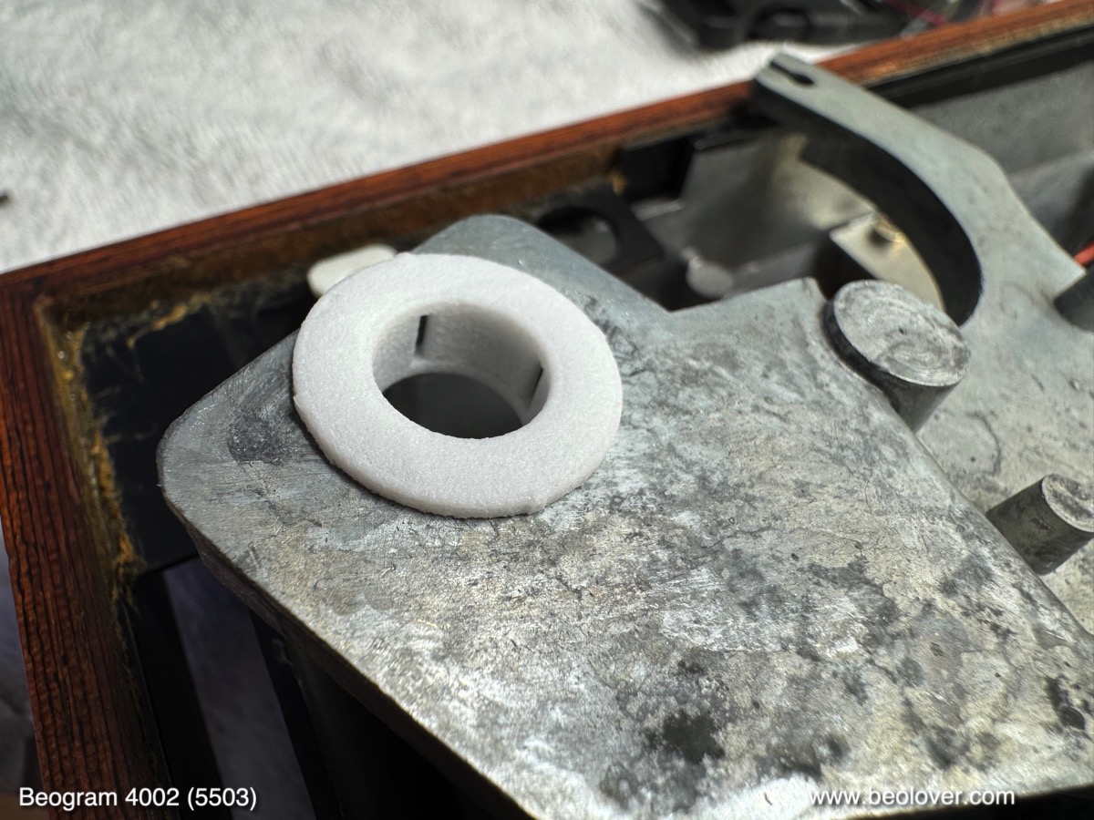
When aligned properly, the three round connection vias on the Beolover board are aligned with the respective solder pads where the board connects to power and the base of 1TR17. All that needs to be done at this point is to put a bit of solder inside the vias.
It is a good idea to solder one via first and then adjust the board precisely, while making sure it is fully flat on the original board surface. If it is not flat or misaligned, it may be difficult or impossible to adjust the plastic ruler for proper function of the position sensor.
This shows the plexiglass ruler assembly bolted back into place. 
Adjust the ruler that runs at a constant ~1mm distance from the front-facing part of the sensor during the entire travel of the carriage.
Flipping the switch in front of the sensor activates the on-board LED:
The LED makes it easy to test the proper functioning of the sensor. It should light up whenever a black bar passes between the legs of the sensor.

After installation of the sensor, the Beogram reliably recognized the runout grooves of all records I played. Beautifully!


Wednesday, January 7, 2026

Beogram 8002: Carriage Runs into Mechanical Limit During Carriage Return

A Beogram 8002 that I am currently working on exhibited a strange issue after I had it fully restored and mechanically adjusted (i.e. the arms were perfectly orthogonal to the carriage rods and the end switch was set to a position where the arm would drop properly at the LP setdown point): Whenever I activated STOP or the arm auto-returned after playing a record, the carriage would bump into its mechanical limit and tilt upwards a bit. Not very beolovely! This meant the carriage motor somehow did not shut down soon enough after the end switch activated. 

This was odd, since the end switch was adjusted for a perfect arm drop onto an LP run in groove, i.e. this issue could not be fixed by changing the end switch position a bit inward so the carriage would travel less far towards its home location. On another 8002 that I have currently on the bench everything worked nicely, i.e. the carriage traveled not as far after triggering the switch and the carriage did not bang into the rod support.

After a bit of head scratching I set up my portable DS-213 oscilloscope to do some measurements on these two Beograms. I measured one of the rotary encoders (blue) vs. the carriage motor voltage, hoping to learn something about the microcontroller timing of the carriage motor operation.

This figure compares the measurements for the problematic unit (top) and the normal one (bottom):

The problematic unit has a 100ms delay between switch activation and shut down of the carriage motor. I should point out here that the stop of the encoder signal coincides with the switch activation since the switch not only interfaces with pin 32 on the uController, but also directly turns off the power to the IR diode in the encoder.

A good question here is 'why did they set it up like this and not just use the encoder steps to determine an exact end of travel for the carriage?' Oh, the mysteries of vintage B&O!..;-). I would certainly not have designed it like this. Maybe a constraint was that not enough I/O pins were available and they had to combine a number of control items on a single pin.

Anyway, in contrast to this measurement the 'normal' 8002 only shows a ~70ms delay. In other words, the problematic 8002 runs the carriage motor about 50% longer than the good one after the end switch is triggered. This suggests that the two microcontrollers have different programming since the motor shutdown is directly controlled by pin 26 (">>") of the controller. In other words there was nothing to fix. Everything was mechanically and electronically in good shape, just the controller did some slightly different controlling!

My big question was how to alleviate this issue without the ability to change the firmware on the chip. In the end I saw only one way to deal with this: Slow down the carriage speed a bit during return to the home position. Luckily, there is a pretty straight forward way to do this!

This shows the relevant portion of the circuit diagram:

The shown circuit snippet is the half of the motor H-bridge that takes care of rightward (>) motion of the carriage. The opamp IC2 drives the TR3/4 push-pull stage that provides the motor current to OM1. The opamp itself is controlled by comparing the voltage at the + input with the voltage at the - input. The + input is connected to pin 26 of the uController via D7 and to the >> photoresistor in the black box on the keypad PCB via D8.
The voltage coming from the >> photoresistor ranges from 0.62V (if the calibration screws are adjusted properly) to about 3.2V depending on how hard the >> button is pressed.
This told me that the voltage control range tops out at about 3.2V, corresponding to full speed of the carriage. When carriage return is activated by pin 26, however, it applies the full logic voltage of about 4.8V or so, reduced to about 4.2V by D7. This means the the opamp is driven into saturation and puts out its maximum voltage.
My goal was to reduce the carriage speed enough so the carriage would stop slightly before from the mechanical end of travel during the 100ms after the end switch is triggered. This meant I had to reduce the voltage after D7 below 3.2V. I added a 1MOhm trimmer between D7 and the 1MOhm resistor R34, thereby forming a voltage divider that would allow me adjusting the voltage at the + input down to ~50% with the trimmer. For this I removed D7 and put it on the solder side of the board together with the trimmer for better access. Here an impression of this temporary experimental setup:
As expected the voltage yielding a sufficient speed reduction to prevent crashing the carriage was below 3.2V:
This voltage corresponded to ~840kOhm trimmer resistance (trimmer needs to be disconnected for an accurate measurement). With this resistance in place the carriage stopped about ~1mm before the mechanical end of travel, which in turn corresponded to a 9 mm distance between carriage and encoder housing:
All this was measured with the switch set to a position where the arm would drop perfectly into the center of the run in groove allowing time for the output relay to open before the needle would meet the music:
After this successful experiment, I replaced D7 with a small replacement circuit composed of a 820kOhm 0603 SMD resistor and the original diode on a Dremeled 1x6 piece stretch of prototyping board (it seems despite the 'analog' appearance of these 1980s boards they actually put the solder points on a 0.1" matrix!..;-):
Here an impression of the little board replacing the originally lonely D7 on the component side:
After this I tested the unit again and everything still worked! A promising sign!...;-). All good again in Beogram 8002 land! I should point out here that the 'apparent speed' of the carriage return only changed little, i.e. the casual observer will most likely not notice that the return speed was reduced a bit.
On to writing the main post about the restoration of this unit!


Sunday, January 4, 2026

Beogram 4002 (5503): Installation of a New Carriage Motor

I recently did a warranty repair on a Beogram 4002 (Type 5503) that I had sold earlier in 2025. It needed a new solenoid switch. My customer decided to also get a new Beolover Carriage Motor for Beogram 4000, 4002, and 4004 installed, while the unit was on the bench.

The new motors make less noise and vibrations. They also run at a lower current than the original motors. This puts less stress on the H-bridge transistors, which have a tendency to fail occasionally.

This shows the original motor still installed:

I unsoldered the two leads and removed it:
This shows it opened up with the new motor next to it for comparison:
The new motor is a bit shorter, i.e. the leads can be conveniently fed through the cutout in the bottom of the enclosure:
This shows it installed:
I tested the unit and as usual the carriage is now running much more quietly. Beolovely!


Friday, October 10, 2025

Beogram 4000: Carriage Returns Home Immediately After Setting Down on the Record

Oh well, the Beogram 4000 that I restored in January 2025 came back to my bench exhibiting an issue I had not experienced before:

After pressing ON the carriage went and found the LP setdown point and put the arm down. Immediately after hitting the run in groove, the carriage returned home with the arm down. It did that at a fairly high speed. Once home the unit shut off and the arm lifted.

Since the << and >> buttons worked fine with the arm up, a problem with the H-bridge was unlikely. This meant there must be an issue with the tracking sensor.

The Beogram 4000 features two photoresistors FC1 and FC2 that control the reverse and forward directions of the carriage motor (later 4002/4 models are differently set up, with only one photoresistor for the forward direction). This means the dual photoresistor tracking sensor can control the carriage in both directions, forward and reverse. The carriage is at rest when the forward and backward currents through the H-bridge (i.e. the motor) just cancel out. This condition is reached when the aperture in the tracking sensor illuminates both photoresistors with the same intensity, i.e. when it is positioned just between the photoresistors. If everything is properly adjusted, this condition coincides with the tonearm being parallel to the sensor arm. As the arm gets pulled towards the record center during play the arm gets deflected laterally, which causes the forward current to become larger than the reverse current, and the carriage starts moving forward, following the motion of the arm.

A consequence of this setup is that if one photoresistor circuit is not working properly, the carriage motor will already see a significant current even with the tonearm in parallel alignment, and the carriage will start moving. If the failed photoresistor circuit is the one that controls the forward motion, the carriage will always go reverse, independent of the lateral deflection of the tonearm.

With this in mind, I started examining the forward direction circuit. A good rule of thumb with the Beogram 4000 is that 90% of its issues are typically caused by bad contact terminals in the many switches, or by a wiring problem. The Beogram 4000 is an early 1970s design, when wire-to-board connections were still hardwired (instead of using modern wire-to-board headers and plugs, which are mechanically much more resilient). These soldered wires have a tendency to break off at the solder terminals when the Beogram is handled or transported.

This personal 'statistic' was confirmed in this unit: When I had a closer look at the wiring I immediately found the problem. The wire connecting the forward photoresistor FC2 to the H-bridge was broken off at its terminal on the main PCB (yellow marking in the photo):

I cleaned wire end up and soldered it back to the terminal. And the deck was operating normally again! I will play this Beogram a bit and then it should be time for sending it back to its owner in Australia!


Thursday, April 10, 2025

Beogram 4002 (5503): Intermittent Tracking, Installation of New Carriage Motor and Restored Keypad and Update to Latest Beolover State-of-the-Art

I recently received a Beogram 4002 (5503) that I had restored in early 2020. After running for a while it came back in August 2023 with a fried H-Bridge. The H-Bridge is responsible for driving the DC carriage motor. It allows reversing the current direction even if there is only a single positive voltage rail in the system. It does that with transistors that act as switches to reverse the polarity on the motor leads. These transistors need to be able handling the motor current. If everything goes well, the current capacity of the transistors is safely above the current drawn by the motor in all operational situations.

Electric motors draw more current when they run under load since they run slower at the same applied voltage. The slower RPM causes the motor back-EMF (the self-induced voltage in the motor, which is opposed to the driving voltage) to be lower, so more of the applied voltage arrives at the motor coils, which in turn increases the current in the motor windings. This is a great feature of electrical motors since it means maximum torque at zero RPM, great for burning some rubber at a green light to impress ICE vehicle drivers (whose torque-to-RPM ratio is reverse: Minimum torque when the car is at rest and maximum torque when it is at speed...;-).

But this also means that if a mechanical system that is driven by an electrical motor develops more friction over time due to hardened lubricants or dry motor bearings, the motor will draw more current than when the system was new.

I finally came to realize over the years that this may be the root cause for H-bridge failures in Beogram 400x. The H-bridge transistors are able to handle currents of 1 Amp max. And when everything is according to spec fast forward or reverse typically draws about 0.1-0.2 Amps. 5x is a decent safety margin. But when there is additional friction, the current can get dangerously close to 1 Amp or even exceed it. This is evident from the often found blackened PCB surfaces under failed H-bridge transistors.

The main reasons for this issue are the carriage motor itself and hardened lubricants in the carriage translation mechanism. The latter can easily be addressed by cleaning and re-lubricating, but in the case of the motor replacement is necessary. In difference to the later DC platter motors, these motors cannot be rebuilt easily. This was the reason I designed a replacement motor that draws less current than the original motors at a similar torque. Due to its modern design it also creates less vibrations and noise compared to the original motors. This post describes an evaluation of my design.

So I am not really surprised anymore that this Beogram came back again with carriage drive issues considering the earlier H-bridge issues. This time it sometimes stopped tracking. An indication that the carriage motor developed even more friction in its bearings since the last visit. 

Therefore, the first step was to replace the carriage motor with the new Beolover Carriage Motor for Beogram 4000, 4002, and 4004:

This shows the original motor in place:

I extracted it and opened the enclosure up:
Then I installed a new Beolover motor:
It is a bit shorter, which permits feeding the leads through the hole in the enclosure bottom for convenient routing. This shows the motor in place:
After the motor I also replaced the H-bridge power transistors, which were potentially compromised due to the too high current draw of the carriage motor. This shows the H-bridge as I left it in 2020:
I removed the four transistors:
1TR25 definitely got a bit hot as suggested by the browned PCB surface under it. This transistor participates in driving the carriage left towards the home position. This is probably the most stressed one since every time the carriage returns home it goes full speed for maybe 20 sec giving this transistor some time to heat up.
I installed a new set of transistors and then it was time to update the RPM panel backlight LEDs. I had replaced the bulbs in 2020, but back then I still used homemade boards featuring red/green LEDs tuned to yield an incandescent sheen. This shows the bulb covers of the RPM panel:
I removed the covers, which revealed the LED boards I had installed:
I removed these PCBs. This shows the old design together with my current solution:
The new boards solder directly to the solder points of the original light bulbs. They essentially act as an extension of the circuit board. This shows them installed:
They give the RPM adjustment scales a nice incandescent-like backlight:
My customer also wanted me to update the main capacitor setup and the wasteful linear regulator based 22.8V power supply. This shows my work of 2020, when I still used big radially leaded capacitor cans similar to the original setup:
This board solders directly to the existing leads that previously connected to the big capacitors. The board also replaces 0TR1 (to the right of the platter motor in the picture) that regulates the 22.8V rail in the original setup. My board uses a modern buck converter to create the system voltage from the rectified DC coming from the transformer, which is much less wasteful and results in a cooler running and less energy using Beogram.
Looking at my notes from 2020, I saw that I did not de-magnetize the solenoid plungers yet as a standard restoration item. These plungers often get magnetized to various degrees, which can result in sluggish arm lifting. During auto-return at the end of a record this can cause the tip to drag over the platter for some distance before it finally lifts up when the spring overcomes the magnetic attraction. For demagnetizing the plunger the solenoid has to be extracted and then the plunger unscrewed from the angled bolt that connects the solenoid lever. This shows the solenoid in place:
Indeed the extracted plunger was magnetic. I usually test this with a ferrous set screw. If the plunger attracts the screw it needs demagnetizing:
After using my tape head demagnetizer on it a bit the screw was not attracted to the plunger anymore, 
so I put everything back together.
I also found that the sensor arm LED replacement was still one of my early versions based on a home etched flex PCB that I folded into the small bulb compartment:
This shows the extracted old part in comparison with my current approach, based on a small PCB and a 3D printed alignment aid:
This shows it in action. It uses a warm white LED that has enough red photons for lighting up the B&O logo in a realistic warm red:
Next came the replacement of my original early design transport lock bushings. The one on the left in the picture below shows my original design, which has a much wider wall thickness. Over time I came to realize that it makes the adjustment of the sub-chassis much easier if there is a bit more room around the lock bolts. So I re-designed the bushings with thinner walls (shown on the right): 
An added nice benefit of these new bushings is that the sub-chassis can move much more before it hits the lock bolts. This gives gives it a much more supple feel when the platter is touched and just freely swings. This shows one of the bushings installed:
Their two halves are simply pushed in from the top and bottom, which makes installation very easy. This shows the liberated chassis during the installation of the bushings:

The final update was to replace the smudged keypad with a new Beolover replacement. This shows the original keypad:
Most of the 4002 and 4004 keypads develop such use traces over time. First it starts with such 'smudges', basically polished areas caused by friction with the fingers when operating the Beogram. As time goes on the coating wears fully through. Luckily co-Beolover Beomazed recently succeeded after a long time of trial and error with reproducing the keypad plates. His plates are completely new and carry a modern resilient coating that promises to last for a while. This shows the restored keypad:

Absolutely stunning. They really look like the original pads! Read here how he does it!
If you are interested in getting your keypad restored, please visit here.
I installed the renewed pad in the Beogram. This is how this beauty looks now!:
And then it was finally time to enjoy this fully Beolover state-of-the-art restored Beogram with one of my favorite records by Chico Hamilton: "chic, chic, chico", which he recorded in 1965 on Impulse! I have the stereo version AS-82. He looks really chic on this one!...;-). A stunning record that has just the right amount of 'avant-garde edginess' as one would expect from an Impulse! record! A great match for this beautiful Beogram 4002!:
I will now play a few more records on this deck and then it will be time to send it back to its owner in California!