Featured Post

Beolover SyncDrive: DC Platter Motor Replacement for Beogram 4002 and 4004 (Type 551x and 552x)

Late Beogram 4002 and the 4004 (Types 551x and 552x), which have DC platter motors instead of the earlier synchronous AC motors usually suff...

Showing posts with label photoresistor. Show all posts

Sunday, April 26, 2026

Beogram 4002 (5503): New Monolithic Beolover Carriage Position Sensor for AC-Motor Beogram 4002 (Types 550x)

A little more than a year ago I designed a replacement part for the carriage position sensor PCB in DC platter motor Beogram 4002 and 4004 (Types 551x and 552x). This board takes the guesswork out when the carriage position sensor does not work properly. The original design is fairly sensitive to the alignment between the IR diode and the photoresistor, as well as the alignment of the ruler relative ot the sensor, and it can be tedious to get everything properly adjusted.

The Beolover Carriage Position PCB for Beogram 4002 and 4004 (Types 551x/552x) is based on a modern monolithic IR photo-interrupter and circuitry that generates a clean and precise digital output signal for driving 1TR17 on the main PCB.

Sadly, this solution only works in the later DC motor Beograms. The earlier Beogram 4002 with AC platter motor has a much more complicated hard-wired carriage position sensor PCB that is not very easily replaced. But when I recently restored an AC motor Type 5503 Beogram 4002, and it gave me grief with detecting the runout groove reliably, I thought it would be nice to have a solution for these models, too!

Since replacing the entire board is complicated and unnecessary, I designed a replacement for just the sensor part of the board. I designed a board that simply piggybacks onto the main PCB, replacing only the original sensor bulb and photoresistor. This board adapts the same reliable circuit that I used on the DC motor PCB. 

This shows the final version of the Beolover Carriage Position Sensor for Beogram 4002 (Types 550x):


Let's see how it is installed:

This shows the original setup. The photoresistor is in the black housing in front of the 'plexiglass ruler' bolted to the carriage assembly:


After removing the two screws that hold the ruler assembly in place, it can be removed. This reveals the black bulb housing under the ruler.
Here is a view from a different angle (I already had the orange capacitor and white solenoid resistor replaced when I took this photo):
After removal of the bulb cover, the bulb is visible:
The first step for the installation of the new Beolover Carriage Position Sensor for Beogram 4002 (Types 550x) is removing both the photoresistor and the bulb and cleaning the five solder pads indicated below of all solder:
This is best done with a desolder gun since the pads need to be clean and flat so that the Beolover board can be placed onto the original board surface. The board needs to be aligned as shown in the picture below:
This shows it aligned and soldered in place:
When aligned properly, the three round connection vias on the Beolover board are aligned with the respective solder pads where the board connects to power and the base of 1TR17. All that needs to be done at this point is to put a bit of solder inside the vias.
It is a good idea to solder one via first and then adjust the board precisely, while making sure it is fully flat on the original board surface. If it is not flat or misaligned, it may be difficult or impossible to adjust the plastic ruler for proper function of the position sensor.
This shows the plexiglass ruler assembly bolted back into place. 
Adjust the ruler that runs at a constant ~1mm distance from the front-facing part of the sensor during the entire travel of the carriage.
Flipping the switch in front of the sensor activates the on-board LED:
The LED makes it easy to test the proper functioning of the sensor. It should light up whenever a black bar passes between the legs of the sensor.

After installation of the sensor, the Beogram reliably recognized the runout grooves of all records I played. Beautifully!


Thursday, April 20, 2023

Beogram 4002 (Type 5513): Replacement of Carriage Position Sensor Photocell

Having worked on quite a few Beogram 400x in the last 10+ years I started thinking 'I saw it all'. But if there is one thing one can rely on with these beautiful designs: They will always come up with new challenges. This time it was a failing photocell in the carriage position sensor. Usually, this sensor fails due to a dead light bulb (or IR LED in later models). Or due to a broken photocell housing, causing the photocell to bend away from the 'plexiglass ruler', which can cause reliability issues.

So when I restored this unit, and it behaved inconsistently when trying to find the LP setdown point after pressing start, I naturally assumed it was the IR LED, which this later 5513 Type featured.

I replaced the LED with an orange LED and adjusted the brightness to get the prescribed 5V at the photo sensor cathode. Then I ran the unit again, and it found the LP setdown point! Case closed, I thought and I played a few more records.

Then out of a sudden it would not find the setdown point again and the cell voltage was off by a couple volts. I thought maybe the brightness adjustment trimmer had an issue due to oxidation, and so I replaced it with a modern 25-turn 25 kOhm encapsulated unit. Then I adjusted to get 5V and tried again. This time it immediately failed and so I started thinking, 'what is left to replace'. The photocell came to mind, but I never had to replace it so far, and I was able to adjust the 5V, so it should be o.k., I thought...that led me to replace TR17, which translates the photocell response to standardized ~20V pulses that can be interpreted by the control system of the deck. I put in a new 547B and tried again. To no avail.

At this point I finally believed it must be the photocell. I disconnected the carriage PCB and connected the cell to the multimeter set to resistance. Then I shone a strong LED flashlight on the sensor, and indeed the sensor responded intermittently. The resistance dropped, and then it went open contact, and then the process repeated itself. Whatever the reason, this was not o.k.

Since this diode-based photocell simply acts as a photoresistor in this circuit, I decided to try replacing it with a standard photoresistor. But first I had to re-design my photocell housing to be able holding such a resistor securely in place. This shows the redesigned set-up:

I basically gave the insert some additional features that matched the resistor shape. This shows the resistor inserted:
And while pushing the insert into the main housing:
This shows the new sensor in place opposite the orange LED that I installed earlier:
A shot from the back:
I had to try out a few different photoresistors before I was able to make this work properly. It turns out that the widely available GL5539 type works reliably under various ambient light scenarios. Note, that it may be necessary to adjust the LED intensity with R88 in order to get a good contrast on the photoresistor that TR17 is reliably switched off and on depending on whether a black stripe is in front of the sensor or not. This is best done with a voltmeter connected to the collector of TR17.


Saturday, July 1, 2017

Beogram 8000: Final Steps

I was kind of lucky I suppose in finding the intermittent pause culprit on the first suspect. However it was the most likely when reviewing the problem. Even though the behavior was intermittent it lined up with a problem Beolover had on a Beogram 8002 project earlier. After replacing the Beogram 8000 original control panel board with one of my spares -


the result has been over twenty error-free record plays.

Returning to the original control panel board to look at repair options I examined the LDR (photoresistor) devices for the forward and reverse controls.


Visually examining them and testing their resistance with different light sources didn't reveal any problems. These devices can become unreliable over time and exhibit the intermittent behavior I experienced so I decided to apply the repair Beolover did on the Beogram 8002.

I ordered the same LED from Newark and some GL5549 LDR devices from a couple of different sources. Replacing the original lamp with an LED requires a load resistor so I used the 1K ohm value Beolover had set his to.


Using the same parts I was hoping the fix would just be a quick install, test and go operation. Unfortunately I found that these GL5549 LDR devices vary in performance by quite a bit. It took quite a while to find a pair of these new LDRs to match and be around 20K ohms when in place on the board.

After finally finding a couple of acceptable LDR devices to try I mounted them with some temporary glue to secure them in their respective mounting slots.


I prepared the control panel board for re-installing into the Beogram. That included adding my little LDR test connector. This time I used 30 gage hook-up wire so the test connector can be left in the control panel. I matched the wire colors to what the Beogram 8000 colors are for the LDR measurements. That makes it easier to remember later if I have to retest the LDR voltages.


The connector is also a female connector so I don't have to worry about anything shorting by it when I leave it in the Beogram.

Testing the reworked control panel board with the new LDRs was interesting. I ended up having to re-adjust the position of one of the LDR devices. That is why I use glue that isn't permanent. Eventually I was able to get the forward and reverse LDRs adjusted within the 600mV - 700mV range necessary for successful operation. The service manual originally asked for 620mV but later updated that value to 650mV. I talked to another Bang & Olufsen technician who told me a solid value between 600mV and 700mV is sufficient.


As you can see in the picture above, the adjustment for a working forward and reverse operation resulted, again, in quite an imbalance in the adjustment screws of the control panel board. The voltages are stable though so I am going to run another play test with this board just to see what happens.

For this project though I am inclined to go with the replacement control panel board that I ran the twenty successful record plays with. The forward and reverse LDR controls are closely matched on that board and I feel will be more of a sure thing. This replacement repair is looking good but I will feel better about it if I can do a long term test with it.

There is one more issue that cropped up during the play testing of this Beogram 8000. Another intermittent problem but one that was easily recognized. A couple of times after a record completed play I noticed that the phono mute did not occur. That means the Beogram phono mute relay is acting up. This picture shows where the muting relay is located. It is easy to get to but does require opening up the Beogram case again. Oh well.


I hadn't planned on replacing this relay but since it has come up I asked the owner if he would like the phono grounding switch to be added. This is a convenience option that Beolover has been doing on Beogram 400x and 800x turntables. The added switch gives a user the option of setting the turntable up as it is originally or shorting the phono signal ground to the Beogram chassis ground.

This is a nice feature for Beogram owners that use the turntable with a non-B&O amplifier. I pair a lot of my Beogram units with my Yamaha C2a, C2x and C-70 preamplifiers. Those pre-amps support two turntable inputs but require using RCA jacks. When I add the DIN to RCA converter I get a hum in the phono signal unless I attach an extra grounding wire on the adapter to the amplifier chassis ground lug. With this switch added to the Beogram I can short the phono signal grounds to the chassis ground in the Beogram and not need the extra grounding wire on the cable adapter.

It's doesn't seem like a big deal but it is nice to have options so we are adding the switch to this Beogram.

First I need to removed the faulty muting relay.


This muting relay is different than the one in the Beogram 8002 turntable where Beolover was able to replace it with a new Omron sealed relay device. That relay pin layout is not a match for this Beogram 8000 output signal board. My only option here is to take a newer output relay from one of my later model Beogram 8000 spares.


If I didn't have a spare I would have removed the clear plastic cover and tried to clean the relay contacts. That still might not have solved the problem if it is in the relay coil.

I installed the new muting relay and then attached the grounding switch.


I used some hot glue in the gap between the output board case and the switch case. This helps secure the switch.

Now it is back to the record play testing again. Success of these tests will result in this Beogram being packed up to return home.


Saturday, June 24, 2017

Beogram 8000: Trouble-Shooting Test Phase 1

I made the choice to try switching the Beogram 8000 control panel board first in the trouble-shooting of the intermittent record play interruption. This is the problem where occasionally the Beogram tonearm lifts to the Pause position while playing a record.

This is the easiest thing to check first and I kind of suspect the photo resistor circuit in the control panel on this Beogram anyway. When I made the service manual adjustments earlier in this restoration I noticed the adjustment for the adjustment screws were quite a bit different between the forward (<<) and reverse (>>). The adjustment screws control how much light shines on the photo resistor. The service manual says the normal voltage across those resistors (when forward and reverse are not engaged) is 620mV.

The following picture shows the control panel board removed. The position of the adjustment screws are where they needed to be to get the 620mV measurement. The difference in position of the two screws make me think one of the photo resistors is weaker than the other. Perhaps that is the reason for the fault I am trying to fix.


On the spare control panel board in the background you can see what I expect their positions to be like in relationship to each other.

One annoying thing about this adjustment is that B&O didn't provide good test points to check and adjust these controls without opening up the Beogram. It is easy to open just the control panel so if there were a nice test connector there I could check and make this adjustment after the Beogram is closed up.


The P5 connector pins 3, 4 and 6 are the nodes necessary to measure for this adjustment.
So I decided to add a test connector that I can access with just the control panel open. I also decided to do this test with one of my spare Beogram 8000 control panel boards.


I used a female connector for the end so I could leave the test connector attached. The picture above shows the test connector with the male test plug attached.

The test connector works great!  The Beogram 8000 is all closed up except for the control panel and I can easily use the test connector to make the adjustments.


I discovered that I will have to remove the test connector in this first attempt as the 24 gauge wires are too big and interfere with closing up the control panel all the way. If I want to have a "leave in" test connector I will have to go to a 30 gauge wire.

For now though it is time to return to the record play testing of this Beogram to see if the control panel was the problem. I am using the spare control panel board with the test connector and adjusted to the voltages specified by the service manual. On this spare board both adjustment screws are pretty symmetrical so that is a good sign that both photo-resistors are a pretty good match.

I am now on the last side of the second record play test. Only about eighteen more uninterrupted record plays (36 sides) to go for me to say the problem is fixed.


Friday, February 26, 2016

Beogram 8002: Strange Behavior - After PLAY Arm Just Moves 2 cm, Then Stops

A Beogram 8002 from Australia arrived for some TLC. The problem at hand was that after pressing PLAY the arm just traveled in for about 2 cm and then it stopped. While this was very reproducible on my bench the previous experience was more intermittent in that sometimes the deck would start playing normally, but then after a few minutes it would suddenly stop. 

I opened the deck up and my first guess was rotary encoder trouble. If the encoder on the carriage spindle does not work properly, the normal response of the control system is to stop playing after about 2 sec. And 2 sec is about the time it takes to travel 2 cm. This shows the relevant sections of the circuit diagram:


The rotary encoder section is in the top left quadrant. The IR diode (OPE1) is powered via the 5V rail and a 150R resistor. This results in about 1.3V at the diode. When I measured I got 5V, indicating that no current is flowing through R1, meaning that the diode had gone open circuit. This is the typical failure mode of these devices.
This shows the rotary encoder assembly removed from the aperture wheel section:
The bottom unit is the IR diode, the upper two units are the two photo diodes. Their voltages are fed into IC1/IC2 and after amplification are fed into processor pins 28/29 ("Slide Tacho"). When this signal is flat while moving the carriage (slide) the processor stops the movement after 2 sec. I replaced the IR emitter with a Optek OP240, which can be had in the same package as the original unit:
This restored the 1.3V at the diode and I was now able to measure the proper encoder signal at plug 6 Pin 13/14, but the problem did not go away. Frustrating!

My initial guess was that the encoder signal did not arrive at the processor pins. So I removed the PCB, opened up the processor EMI can and ran the unit, while measuring directly at the processor pins. Micro grabber jumper cables are really nice for such measurements! Here is an impression:
Well...the signal arrived at the processor. And I also noticed during these experiments that the deck would sometimes work, especially when freshly plugged in! The plot thickened! Working on B&O vintage units for some time now, I immediately put my money (I lost...;-) on a cracked solder joint or a hair line fracture in the PCB. So I set out to re-solder all relevant connections. Here is an impression of the processor board, solder side:
Well, al this effort did not fix the problem!
So I hooked up my oscilloscope and watched the relevant signals on the processor inputs as the issue unfolded. Finally, when monitoring pin 31 ("lift manual") I got these traces:
the green and yellow ones are the encoder signals on 28/29. The red one is the signal at pin 27 (<<), which essentially controls the carriage servo. The blue line is the signal on pin 31. And what we see is that the signal on this pin increases, and at about 3.5V (which is about where a logic HIGH starts on 5V systems) pin 27 caves turning the servo off, causing the carriage to stop as we see from the petering out signals on the encoder diodes.
This immediately suggested that something gave the processor the impression that the arm needs to be lifted and the carriage stopped.

Considering the relevant sections of the circuit diagram, it was clear to me that somehow the signal on the input opamp IC2 (same opamp package as the IC2 that amplifies one of the encoder diodes) that is hooked up to pin 31 must go high. The only way that this can happen is when the resistance of the photoresistors R9 or R10 in the << >> control housing gets too large without pressing one of the <</>> buttons. The way this control system works is that when these buttons are pressed an aperture is driven in between the light bulb IL1 and the either R9 or R10. This gradually increases their resistance, thereby raising the voltage at the corresponding IC2 turning on the carriage servo OM1 in either forward or reverse direction. While this happens the motor control signal is also fed into the opamp that connects to pin 31 via diodes D5/D6. 
All this suggested that one of the photoresistors increased its resistance by itself without pressing one of the << >> buttons. The service manual prescribes that the voltage at the resistors as measured at plug 5 pins 4 or 6 needs to be 0.61V when the buttons are not pressed. I measured 1.2V at pin 6 and 0.6 at pin 4. My first response to that was trying to adjust the screws that are in the housing allowing the reduction of the light that falls on the resistors. But I was not able to get the voltage below 1.2V. And that suggested that the photo resistor was either the wrong type or broken. This also explained the 2 sec delay before the deck would shut off, since these resistors are temperature sensitive, i.e. the lamp would heat up the resistors and the bad/wrong one then crossed the threshold at which the opamp started triggering pin 31.

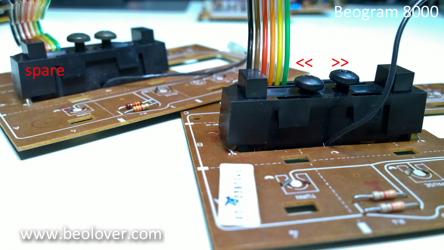
I took the control panel out:
The two screws on the bulb housing are used to adjust the light intensity that arrives on the photoresistors. Then I removed the PCB from the front panel. Here is a look at the panel backside:
This shows one of the photoresistors. 

They are mounted in compartments on either side of the light bulb. Here is a picture with the bulb illuminated.
I measured the resistance on the photoresists on the 'good side' of the assembly. I found about 20k when the button was not pressed. The other side had about 75k, and there was no way to get that down.
Since the manual does not specify what type of photoresistor they used for this assembly, I needed to experiment a bit. So I bought a bunch of photoresistors with different resistances for a 'shootout'. 

A few days later, I received six different types, and I measured their resistance in the cavity with the light bulb on. I finally settled on GL5549, which is widely available on ebay. It is specified to have a dark resistance of 10M and 100-200 under illumination. But that seems to be a fairly weak light intensity. In the Beogram assembly it showed 20k with the aperture fully opened. 
While in there I decided to also replace the light bulb with a white LED (Newark 14N9428) to ensure better long term stability. I used a 1k resistor to limit the current. Here is an impression:
This shows the backside:
After verifying that the light intensity was high enough to yield the 0.61V I put everything back together, adjusted the brightness screws on the bulb housing to get the 0.61V on both sides and then fired up the deck. And it was back in business. So this appears to be fixed!