Featured Post

Beogram Commander Remote Control: Maybe This is the Final Version!..;-)

This is a follow up to my recent post about the redesigned Beogram Commander remote control board, which now works in both (DC-motor) Beogr...

Tuesday, June 30, 2020

Beogram 4002 Type 5513: Houston Beogram #3 Ready for Action Again

The part of the Beogram 4002 restoration I like the most has arrived. All of the tasks are complete except one final series of fun record playing tests in my office. I like to hook the Beogram up to one of my favorite systems and listen to records while I work at my desk. It is so much more enjoyable than watching television....and someone has to do this job ;-).

I am really pleased with this Beogram. There is something wonderful about knowing that this turntable has had a thorough going over.  It is all clean inside.  Beolover did a great job of restoring the platter motor.  There is comfort knowing that all of the control signals have been checked and adjusted to be at the correct levels. 

We didn't do a full cosmetic restoration like on some Beogram units. This one is in decent shape. At some future date the owner might want to invest in a dust cover polishing and a new coating on the control button panel. But for now it is looks great and is performing like a Beogram 4002 should.


Beogram 4002 DC Platter Motor Restoration

A Beogram 4002 DC platter motor recently arrived from Washington State for a restoration. This shows the motor as received:
After a quick bench test for life signs, which yielded the typical rough running noise caused by dry bearings, I took the motor apart to get to the bearings:
the bearings are the two small donuts on the black pad up front. I immersed them in motor oil and pulled a vacuum:
Immediately, vigorous bubbling started from the bearings, indicating that air was drawn from the porous Oilite brass bearing material into the vacuum. This air extraction makes room for oil inter diffusion into the material. This is how Oilite bearings provide lubricant to the shaft. But over time the oil gets depleted, and then it is time to replenish it. After about 72 hours the bubbling stopped, which means that the pores are filled again. I extracted the bearings:
and reassembled the motor to give it a RPM stability test in one of my 4002s with the BeoloverRPM device, which allows logging the RPM in 10s intervals over extended periods of time. Ideal for detection of sporadic RPM variations:
This is the curve I measured over about 24 hrs:
This is as good as it gets with the Beogram 4002 DC motors. Time to send this motor back to Washington State!


Sunday, June 28, 2020

Beogram 4002 Type 5513: Service Manual Checks and Sensor Adjustment for the Third Beogram from Houston

Today I moved the Beogram 4002 from the work bench to the test bench.
This project is heading into the final stretch of restoration tasks.

I went through service manual checks (and adjustments) as well as adjusting the three main sensors in the Beogram: The record detection sensor, the arm position sensor and the tracking sensor.

For the record detection sensor I followed Beolover's instructional video. I had already installed the adjustment trimmer where I could set the baseline 1TR3 collector voltage. That is the DC voltage at the collector when the Beogram is on and the detector is not picking up any signal from the rotating, empty platter.

For the non-rotating platter scenario the 1TR3 collector is adjusted to about 4 VDC. This is also the voltage the collector should measure if a record is present on the platter.


While set up with the DMM I measured and adjusted the tangential arm position sensor for 5 VDC at the collector of the 4IC1 device (when the sensor lamp is shining through a clear section of the position scale).


Now that those adjustments are made I moved the trimmer for the record detection circuit to the component side of the main board where it belongs. Then I set the Beogram up to measure the 1TR3 collector with my oscilloscope when the record detection circuit is reading an empty, rotating platter.


I measured the expected signal. It is actually a little higher than other Beogram 400x units I have restored. It peaks at around 8 volts and drops down to zero volts as the sensor reacts to the sensor lamp hitting the empty Beogram platter.

Now that the detection circuit adjustment trimmer is moved out of the way and over to the component side of the main board I can take care of the various service manual adjustments.

I used my usual gauge to check and adjust the platter to fixed arm height of 23mm.


Next, I adjusted the tonearm set down limit so the MMC stylus sits about a half a millimeter above the low section of the platter rib.


I also performed the usual check for the tonearm length and parallelism of the arm assembly by checking that the stylus travels a straight line from the edge of the platter to the center.


The tonearm tracking force was calibrated to 1.0 gram and I checked that the 1.2 gram position of the knob also measures 1.2 grams on the scale.


After those adjustments I was finally able to adjust the tracking sensor sensitivity. No photos of that as you really can't capture the setting with a still photo. Details of the adjustment procedure can be seen in this Beolover video.

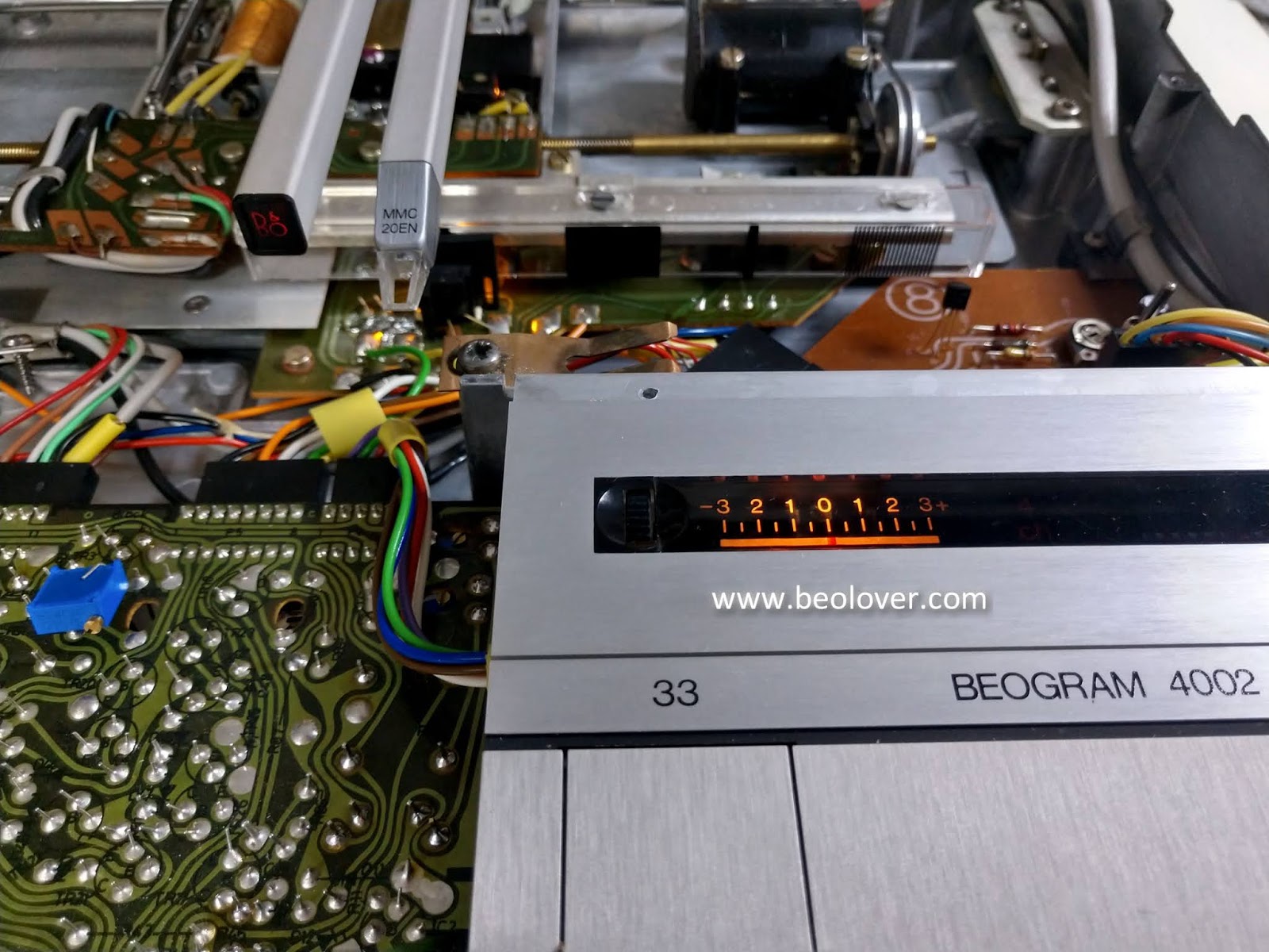
Next were the calibration of the platter speeds: 33⅓ RPM and 45 RPM.


The final adjustments were for the height of the floating chassis to the Beogram deck so the platter surface was level with the deck.

This Beogram is almost ready for some listening tests. All I have left is to reattach the cabinet trim and the dust cover.


Saturday, June 27, 2020

Beogram 4002 Type 5513: Reassembly of the Floating Chassis and Some Initial Checks

The tangential arm assembly component checks have been made and the Beogram 4002 cabinet has been cleaned with compress air. The reservoir capacitors have been replaced and it is time to put the floating chassis back into the cabinet.

I cleaned and lubricated the three suspension lock down screws and the reassembly begins with putting those screws back into the Beogram cabinet. 


Here is a picture of the Beogram with all three suspension locks reassembled. It also shows the platter motor and output board back in place.  You may recall that the platter motor was already restored by Beolover back in March.


Next I installed the control panel, the RPM indicator panel and the arm position scale.


Before installing the platter I tested turning on the Beogram first. I want to see if the arm position and record detector sensors work.

The arm position sensor works.


33⅓ RPM and 45 RPM speed select works as well as the two new Beolover indicators.


Here are the arm position sensor and the fixed arm, record detection sensor.


The arm position sensor, ES and SO switches all work. You can also barely make out the glow from the tracking sensor. It is working. The fixed arm, record detector lamp however looks very dim.

Sure enough, a quick check with the platter installed resulted in the sensor failing to detect the empty platter.

I opened up the fixed arm lamp housing and saw that the lamp is barely on.


After removing the lamp I could see that it is partially burned out.


I thought I might be at a standstill when I discovered that I had already used my last Beolover LED record detection lamp assembly. Luckily I still had a handful of original Bang & Olufsen Beogram 4002 detector lamps remaining.


There...that is the expected output of the sensor lamp.


Now I can move the Beogram over to the testing bench to dial in the sensor voltages, adjust the platter speed, set the tracking sensor sensitivity and run through the service manual adjustments.

Thursday, June 25, 2020

Beogram 4002 Type 5513: Inside Work

The restoration of the Beogram 4002 from Houston continues as I worked on the inside of the turntable. In this post I worked on the tangential arm assembly components and the Beogram reservoir capacitor replacement.

Here is an updated photo of this Beogram 4002 with its chassis and tangential arm assembly removed.


The tangential arm assembly components on this Beogram 4002 are in excellent shape.  Most of my tasks were just cleaning and lubrication the Beogram chassis parts. In the photo above you can see the arm lowering damper removed and disassembled. The parts were nice and clean but the lubrication fluid for the damper was gone. I applied a fresh coat of PMX-200 silicone fluid per the service manual. The tangential drive spindle was also cleaned and lubricated along with the nylon nut (that drives the arm assembly). The tangential arm assembly tracking components were checked and all looked to be in great shape.


Two components I did change out were the tangential arm assembly position sensor lamp and the tangential drive pulley.

I replaced the old plastic pulley with a new aluminum one.


Just for reference here is a photo of the underneath side of the Beogram 4002 tangential arm assembly carriage. It isn't seen very often in restoration photos but is a good thing to examine.
The thin wires from the phono cartridge come out of the base of the tonearm pivot and connect to a transfer board. From there they are picked up by a larger, shielded cable that takes the audio signals over to the audio muting circuit just prior to exiting the Beogram (to a preamplifier).


....and finally here is a photo of the new Beogram 4002 reservoir capacitors. As usual I installed the nice Beolover replacement capacitor assembly.


There were no surprises with this Beogram 4002 turntable and these components are now ready to be reassembled back in the Beogram cabinet.

Wednesday, June 24, 2020

Beogram 4000 Packaging for Shipping: An Update on How to Secure the Carriage

This post is about a change to my packaging instructions for Beogram 4000, 4002, and 4004. I now recommend securing the carriage by using an M3 screw to bolt the carriage directly to the floating chassis (instead of taping the arms cover to the aluminum platters as shown in our videos). 

The reason for this change is that the Beogram 4000 I recently restored came well packaged, but the arms cover suffered unnecessary damage to its labeling:
Sadly, the 'no-residue' Blue Tape that was placed over it to hold the carriage in place during shipping damaged the labeling when I removed the tape. While I point out in my shipping instructions to place some cut to size paper under the blue tape for protecting any labeling from 'lift off', it keeps happening. And it seems that the arms cover has the most vulnerable lettering of all, potentially due to its different aluminum surface finish. It is not brushed like the other aluminum surfaces, and much smoother. 

I recently learned that all Beograms came out of the box with a screw installed that firmly locked the carriage to the floating chassis during transport. Sort of an additional transport lock for the carriage. Unfortunately, the original screws seem to have mostly gone missing. I have never seen one. They probably get lost since they need to be removed completely during the setup of the turntable.
For this reason I came up with a modern replacement, which I will supply from now on with my Beogram shipping containers:

My carriage lock screw fits into the M3 threads that are located under the small hole in front of the solenoid (the bolt threads point to the hole in the picture below):
BTW: This looks identical in many 4002s (the 4004 does not seem to have this feature), just check out the gap between solenoid and PCB.

The carriage lock screw should be bolted down until some resistance is felt, but not too hard. Just enough that it will not come loose during transport. The solenoid wires may need to be pushed aside a little bit when bolting the screw into place.
This shows it installed:
The head clears the aluminum panel by about 2 mm when the bolt is screwed down all the way:
After this is done, it is not necessary anymore to tape the arms down like I showed in my packaging video (please, note that the strip/foam at the end of the arms are still necessary):
If you do not have a suitable M3 screw at hand, you still need to do the tape, but please make sure you put a strip of paper under the blue tape where the lettering is!