Featured Post

Beogram Commander Remote Control: Maybe This is the Final Version!..;-)

This is a follow up to my recent post about the redesigned Beogram Commander remote control board, which now works in both (DC-motor) Beogr...

Wednesday, May 31, 2017

Beogram 4000: Restoration of Arm Lowering and Tracking Systems

The first step of the restoration of the Beogram 4000 that is currently on my bench was to rebuild the arm lowering and tracking mechanisms. This shows the solenoid and the damper that take care of timely and gracefully lowering the arm onto the record:
I removed all the components for cleaning and lubrication:
After reinstalling everything it was time to look after the linkage that connects the damper plunger with the tonearm. It is hidden away on the side of the sensor arm, which needs to be removed to be able to lubricate the pivot point of the linkage:
this shows the linkage removed:
After reassembling everything it was time to adjust the parallelism of the arms. The base of the sensor arm needs to be orthogonal to the carriage rods, and then the sensor arm needs to be parallel to the base. Once that is established, the tonearm needs to be adjusted to be parallel to the sensor arm:
The next step was to replace the incandescent bulb in the tracking sensor with a Beolover LED replacement fixture. This shows the original light source in place:
and removed,
which reveals the aperture that controls the feedback loop to the carriage servo motor. The LED replacement is composed of a circuit board and a 3D printed housing that replicates the original lamp housing:
The LED is in the spot where the filament of the light bulb normally resides:
This shows the LED assembly installed:
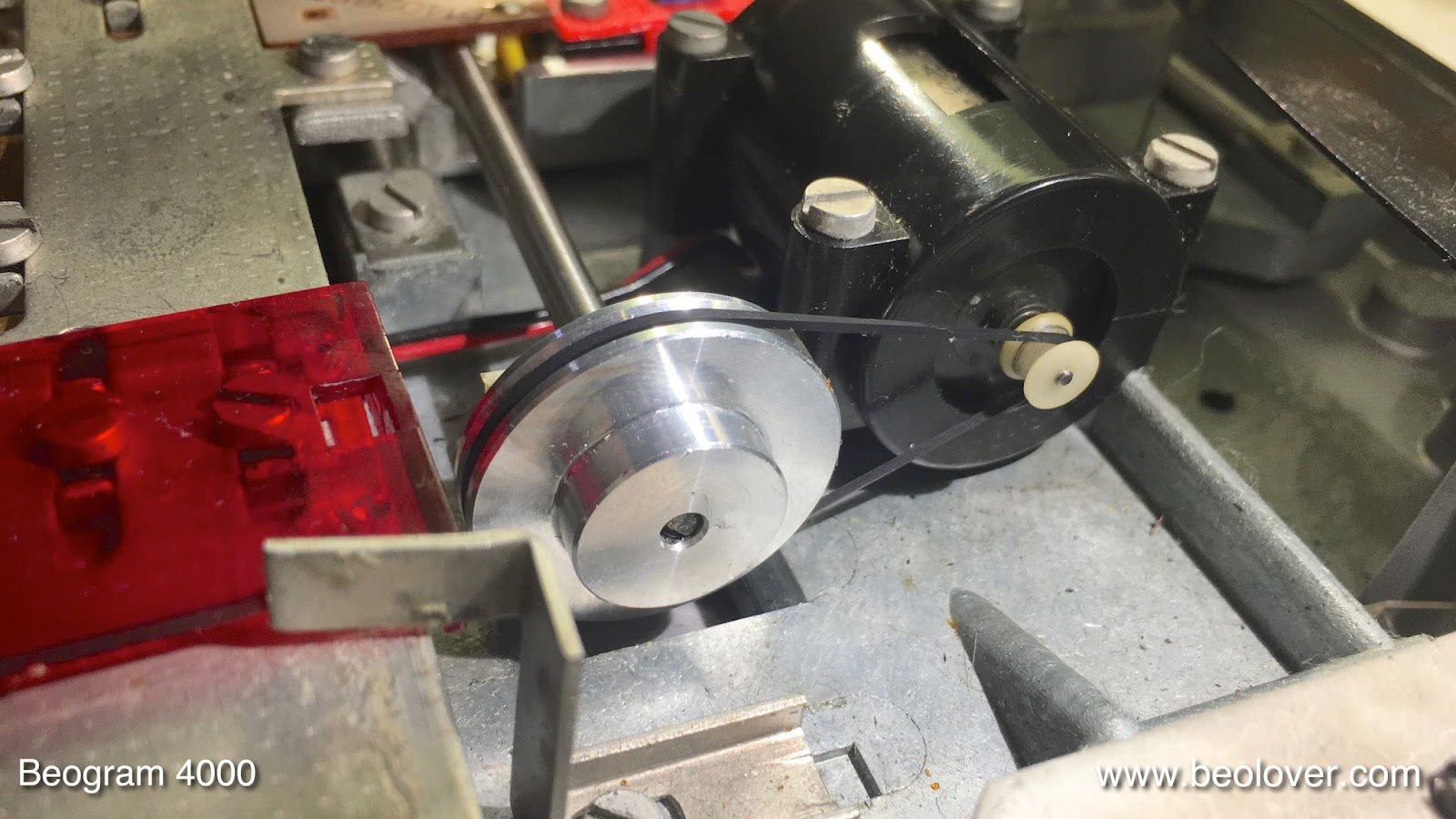
The final step was to clean the threaded rod that drives the carriage and to install a new aluminum pulley provided by Nick (send an email if you want to get one for your Beogram - I'll be happy to get you in touch!). This shows the original plastic pulley:
and this is the awesome new aluminum pulley!:
Beolovely! On to rebuilding the keypad!


Beogram 8000: Recapping The Main Board and Microcomputer Board

The next step in the Beogram 8000 project I am working on is replacing the electrolytic capacitors on the main board and its daughter boards.


Here are the boards mounting in the Beogram chassis.


Here they are removed. I opened the lid to the microcomputer board and the processor integrated circuit device pulled out of its socket. The heatsink compound was a stronger bond to the device than the socket. It makes me wonder about the integrity of the original socket. Note: I was wearing my anti-static band as I always do when working on components like the processor. Those devices cannot be easily found so I don't take any chances.


There are a couple of 1uF electrolytic capacitors on the trace side that will be replaced as well.


The Beogram 8000 main board has a couple of daughter boards attached that have a total of three electrolytic capacitors that get replaced.


The main board recap is pretty straight forward. However, the large silver 2200uF capacitor has a three prong board mount that is the negative lead. I haven't found a replacement with that same mounting option so I always remove the original mounting ring and use it on the replacement capacitor.


Here is the mounting ring soldered to the new capacitor. The ring can be removed with pliers.


To  make sure the assembly is as secure as the original I add a bead of hot glue all around the ring.


This shows the mounting points for the capacitor on the trace side.


Here are the replacements for the two 1uF capacitors.


The two daughter boards


The rest of the main board


For the microcomputer board there is just one electrolytic capacitor to replace. The IC socket for the processor looks a little ragged so I am going to also replace it.


An important note about the microcomputer board 47uF capacitor that gets replaced is the negative terminal is soldered to both sides of the board. So it has to be desoldered from both sides to remove it and you must not forget to solder both sides with the the new one.


Here is the new socket next to the old one. The new socket is a more heavy duty socket.


This is the finished result - New socket and C28 capacitor.


I am not going to close up the microcomputer board assembly yet until I can run an electrical check of the recapping work. There are still three capacitors to replace. Two chassis mounted capacitors and the motor capacitor inside the transformer box.
Those will be in the next post.


Tuesday, May 30, 2017

Beogram 4002 Type 5513: Weekend Update

This weekend I finished most of the electrical work on the Beogram 4002 and reassembled the components in the cleaned up chassis.


For the electrical work the output board was updated to replace the 100uF capacitor and the original relay was replaced with a Beolover direct replacement part that has a sealed relay. A small toggle switch was also installed to allow connecting or disconnecting signal ground from chassis ground on the phono cable.

Here are the original components.


This relay also had the deteriorating insulator underneath it. That material decomposition adds to the unwanted debris inside the turntable.


The new relay doesn't require anything underneath it as it has standoffs built in. Here is the finished output board with the new components.


The reservoir capacitor for the Beogram was replaced. The original part is actually two capacitors in one. The replacement is a Beolover 3D printed adapter that holds two new, replacement capacitors. This adapter is nice because it is designed to mount to the original B&O clamp.

Here are the original reservoir capacitors. Note that this picture was prior to the debris clean up and suspended chassis removal.


Here are the new capacitors in the custom adapter. Technically the smaller, 1000uF capacitor could be removed or disconnected as it is for the CD4 option that some Beogram 4002 units have. It doesn't really do anything for this this Type 5513 turntable. I added a resistor across the 1000uF leads so it will discharge when the Beogram is unplugged.


Another electrical update on this Beogram was the carriage sensor light source. Because the original does go out eventually and due to the age of this Beogram we decided to change it to a new LED.

Here is the original carriage sensor and light source.


I hoped that one of my LEDs I had in stock could be used as a replacement.


However, in testing out the replacement LED I could not get enough voltage from the sensor. The adjustment trimmer, R88, could not adjust the voltage at the base of TR17 to 0.7V as needed.


I switched to a brighter LED and that got me to operating range for the TR17 base voltage but 0.695V is the maximum I could get with this second LED.


I already had to order a trimmer resistor for the sensor arm adjustment so I added some LEDs to the order. They will arrive tomorrow.

However, with this temporary replacement light source I am able to test out that the Beogram electrical updates are functioning as expected.


There were a number of tasks that had to be done when the tonearm carriage was removed so this was the first opportunity to test out those changes. This is always a good milestone in the restoration to reach. Tomorrow I should have the parts I need to finish the electrical adjustments. After that I can get on with the mechanical adjustments.

Monday, May 29, 2017

Beogram 4004 (5526): Final Adjustments and a Test Drive with Herbie Mann!

The restoration of this Beogram 4004 (5526) is finally coming to a close. After fixing the bent alignment pin for the aluminum panel around the platter it was time to adjust the floating sub-chassis and then the platter height. Once this is done, the arm lowering limit can be adjusted so that the needle misses the ribs on the platter should the record detection circuit malfunction at some point:
Once the limit is established, the arm counterweight can be adjusted and then the tracking weight. I usually install a M3 nut at the counterweight screw that one can fix it in place once the adjustment is done. This is a prerequisite when the turntable needs to be shipped and the weight calibration is to survive the trip. This shows the counterweight assembly in its original condition with the retaining washer that holds the adjustment screw in place:
And this shows the nut installed and tightened after calibrating the weight scale:
After this was done, I put on a cartridge and adjusted it to the prescribed 1.2g tracking weight with a digital gauge:
These low-priced gauges are very accurate these days and I highly recommend to get one for the occasional check of the tracking weight.

And then it was finally time to play this Beogram! I selected a recently acquired record by Herbie Mann, which is a pretty unusual and highly interesting album: Stone Flute, which he recorded for his own Embryo Records label in 1970. One can easily say that this is probably Herbie Mann's least commercial album. It is a highly addictive lush soundscape and quite different from his other outputs. In my opinion a seminal 70's jazz album that belongs in any serious jazz collection. Anyway, here is an impression of the Beogram and Herbie after cleaning the record with a CleanerVinyl ultrasonic record cleaner:
A Beolovely combination! Wouldn't you agree?? 


Sunday, May 28, 2017

Beogram 4004 (5526): Adjusting a Bent Aluminum Panel Alignment Pin

When I initially received this Beogram 4004 (5526), removing the aluminum panels took me a while. The main panel around the platter was completely jammed in a 'too far forward' position, which prevented its release by sliding the plinth forward (basically the plinth could not be moved far enough to release the panel). Once the panel was finally off (convinced with a bit of 'gentle violence') it became clear what the issue was:
The alignment pin on the left side was bent forward, which forced the panel to seat too far forward, too. These pins go into holes drilled into the bottom of the panels. This shows the corresponding hole:
The dab of white goo at 5 o'clock is a bit of Alene's glue transferred from the pin, which I used to get me an approximate position of the bent pin relative to the hole when the panel was aligned. After bending the pin a few times iteratively and watching where the glue moved I was finally able to get it properly aligned holding the panel in the correct spot:
On to the final adjustments (which require the aluminum panels to be installed properly)...