Here are the boards mounting in the Beogram chassis.
Here they are removed. I opened the lid to the microcomputer board and the processor integrated circuit device pulled out of its socket. The heatsink compound was a stronger bond to the device than the socket. It makes me wonder about the integrity of the original socket. Note: I was wearing my anti-static band as I always do when working on components like the processor. Those devices cannot be easily found so I don't take any chances.
There are a couple of 1uF electrolytic capacitors on the trace side that will be replaced as well.
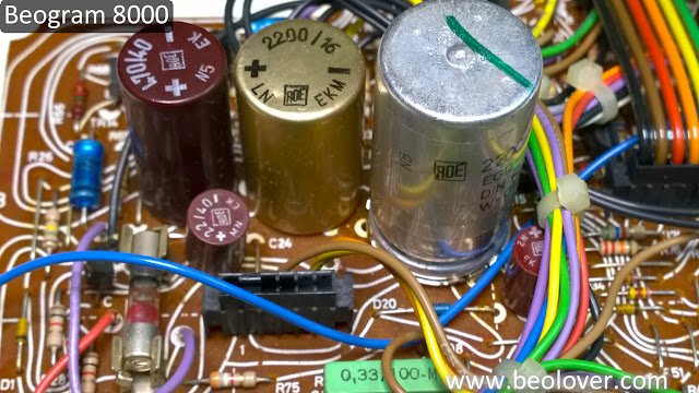
The Beogram 8000 main board has a couple of daughter boards attached that have a total of three electrolytic capacitors that get replaced.
The main board recap is pretty straight forward. However, the large silver 2200uF capacitor has a three prong board mount that is the negative lead. I haven't found a replacement with that same mounting option so I always remove the original mounting ring and use it on the replacement capacitor.
To make sure the assembly is as secure as the original I add a bead of hot glue all around the ring.
This shows the mounting points for the capacitor on the trace side.
The rest of the main board
For the microcomputer board there is just one electrolytic capacitor to replace. The IC socket for the processor looks a little ragged so I am going to also replace it.
An important note about the microcomputer board 47uF capacitor that gets replaced is the negative terminal is soldered to both sides of the board. So it has to be desoldered from both sides to remove it and you must not forget to solder both sides with the the new one.
Here is the new socket next to the old one. The new socket is a more heavy duty socket.
This is the finished result - New socket and C28 capacitor.
I am not going to close up the microcomputer board assembly yet until I can run an electrical check of the recapping work. There are still three capacitors to replace. Two chassis mounted capacitors and the motor capacitor inside the transformer box.
Those will be in the next post.


No comments:
Post a Comment
Comments and suggestions are welcome!