Featured Post

Beolover SyncDrive: DC Platter Motor Replacement for Beogram 4002 and 4004 (Type 551x and 552x)

Late Beogram 4002 and the 4004 (Types 551x and 552x), which have DC platter motors instead of the earlier synchronous AC motors usually suff...

Sunday, January 31, 2021

A Pair of Beomaster 1900 Receivers for Restoration: Unit #1 Reassembly for Testing and a Power Problem

 The next step before testing the Beomaster 1900 was to reinstall the four output transistors that mount on the rear heatsinks. I had removed the heatsinks and the original thermal insulating paste. On the reassembly I like to use modern SIL-Pad thermal insulators. They do a great job and don't have the mess that thermal paste does.

Here are the parts laid out for reassembly.


I like the way Bang & Olufsen chose to mount the transistors to the heatsinks. They use curved, metal spring clips that press the plastic face of the transistor against the heatsink...sandwiching the thermal insulating material in between.

Here are the output transistors reinstalled.


Everything is installed that is necessary to start testing the Beomaster 1900.

It only took the amount of time for me to connect up the variac and dim bulb tester to try powering up the Beomaster to discover a problem.

The Beomaster 1900's +15 VDC power supply was not turning on. No Standby lamp illuminated.
I exercised the main power switch again to make sure it wasn't dirty but nothing.

I unplugged the power cord and started to check around the +15 VDC power supply.  I could not measure anything across its fuse.  I had noticed the fuse holders were badly tarnished but this unit had powered up prior to starting the restoration. I pulled the fuse and it was okay. I just couldn't get anything through it from the fuse holders.

Here are the fuse holder clips and where I removed them from on the board.


Age has not been kind to these fuse holders. I remember now that the original bridge rectifier had been replaced on this Beomaster and there was a large, charred mark under where the bridge rectifier had been mounted. It is likely some big power event had occurred sometime in the past.

In any case I need to order some of these fuse holders on the +15 VDC power supply line.  If I order them today Mouser will deliver them on Tuesday.

The power supply incident got me thinking about all of the input power to the Beomaster 1900. I had seen a bad power switch on a Beomaster 2400 in the past so I should look at this one more closely.

I am glad I did. The switch actually measures good and I did some cleaning on it with Deoxit.  However, I found a cut in the insulation on one of the main power wires delivering line power to the Beomaster.  It probably wouldn't hurt anything but I don't like bare wires where they are not supposed to be.


I will rework the wiring on the power switch and fix that problem while I am waiting for the fuse holder clips to arrive.

Here is the cleaned up and prepared power switch.


Wednesday, January 27, 2021

A Pair of Beomaster 1900 Receivers for Restoration: Installing New Lamps (Unit #1)

I replaced all of the indicator lamps in the Beomaster 1900 today.

For the Bass, Treble and Balance indicator lamps I change from the original incandescent type lamps to LED/resistor type lamp assemblies. The reason for that is the incandescent type lamps generate more heat and I can see from white spots on the red lamp lenses that the heat has had an effect.  The LED lamp assemblies will operate much cooler.

Here is the board with the original Bass, Treble and Balance lamps.  I was out of my LED replacement lamp assemblies so I built more than the three I needed for this project as I know I will be needing the extra assemblies soon.


Here are the new Bass, Treble and Balance LED lamp assemblies installed.
Polarity matters with LEDs so I marked where the positive lead has to go on the board.


For the remaining twelve indicator lamps I replaced the original incandescent lamps with new incandescent lamps that I source from Beoparts. They are the correct type and necessary in these indicators so that the underlying Beomaster 1900 circuits work as intended.

There are two lamps on the volume control board and ten lamps on the selected source and FM tuning indicator board.

Here is the before photo of the lamps. I can see that these are replacements that were probably installed when this Beomaster had its bridge rectifier for the 15 volt power supply replaced.


Here are the new lamps.  All uniform...all the same type.


Now this Beomaster is ready for reassembly then on to the power supply testing.


Sunday, January 24, 2021

A Pair of Beomaster 1900 Receivers for Restoration: Recapping the Tone Control & FM Tuning Board (Unit #1)

The most time consuming tasks of the Beomaster 1900 restoration were completed in the last post.
This post shows the final board that needs capacitors replaced....The Tone Control & FM Tuning Board.
The capacitor replacement is easy. There are just ten capacitors and they are easily accessible. The difficult task on this board is cleaning and repairing the three slider controls (Bass, Treble and Balance).

Here is the Tone Control & FM Tuning Board before photos.


I started with the the cleaning and repairing of the slide controls.

After some disassembly of the Bass and Treble sliders I could see that an early repair attempt had been made in the past. Probably at the same time the bridge rectifier on the main board was replaced (though the two items are not related).

These slide controls have a weak part of their design and that is where the control contacts mount to the sliding control bridge. The small, black, plastic piece of the bridge the contacts fit into tends to break.
You can see where there was an attempt to repair that problem with some glue on the bridge of the bass control.


Here is the slider control for treble.


A good slider control bridge repair kit was probably not available when the glue repair attempt was made. That repair probably worked for a while. Eventually that type of repair will fail again so the fix made today is to use a replacement bridge that is supplied by Martin Olsen of Beoparts.

This photo shows the new Beoparts bridge next to the original bridge for the bass control slider.


Here are the bass slider control contacts mounted on the new bridge


Another task of the slider control repair is cleaning and lubricating of the rails the contacts mate with.
I use some Deoxit and some conductive carbon grease. This bass control slider is ready for reassembly and installation back on the Tone Control & FM Tuner Board.


Here is the treble slider control ready for reassembly.


I am starting to get anxious to listen to this Beomaster receiver.  Still a little ways to go though.

The third and last slider control, the balance control, is a different style of slider. It looks similar to the others but its construction is such that it does not require the repair that the bass and treble controls did. I prefer this style of slider that the balance control has. It seems to be more durable.

It does require cleaning and lubrication though.

Here are the before and after photos of the cleaning of the balance slider control.


Now for the capacitor replacements.
Like the other electrolytic capacitors in the Beomaster these were out of tolerance.
Here is the worst one, a 2.2uF capacitor.


Wow... 6.27uF.

Here is a photo of the restored Tone Control & FM Tuning board.


The final restoration tasks before testing the results is to replace the Beomaster 1900 indicator lamps.
I will do that tomorrow.


Saturday, January 23, 2021

A Pair of Beomaster 1900 Receivers for Restoration: Recapping the Main Board and Volume Control Board (Unit #1)

The restoration work on the main board and on the volume control board is now complete.

The Beomaster 1900 and 2400 receivers are low profile so they look small. I always start out these restorations thinking that it should be easy...but once I get started on the capacitor replacement I am quickly reminded at how many components there are.

Here is the main board as I received it.


Here is the main board after replacing the electrolytic and tantalum capacitors.


Here are some details.

As I like to do, I replace the electrolytic and tantalum capacitors that have values 4.7uF and smaller with WIMA MKS capacitors. Those are the capacitors that look like red rectangles. They are non-polarized capacitors as well.

For capacitance values higher than 4.7uF I use high quality 105°C rated capacitors.
I always try to match the original capacitor's voltage rating.


Just like I have seen in the other Beomaster 1900/2400 units I have recapped, most of the capacitors are out of tolerance by 30% to over 100%.

I always measure all of the capacitors I remove. I won't post every photo but these two give you an idea of what is typically found.

This is an original 220uF capacitor...a little out of tolerance now.


Here is a 2.2uF capacitor.


The new, replacements will make a big difference with the old capacitors being so far out of tolerance.
Here is the new 220uF capacitor, a Nichicon.


The only capacitor I didn't change out was a 10uF tantalum capacitor inside the FM tuner. I did take it out and measure it...it was right on 10uF so I decided to leave it in place.

This first Beomaster 1900 unit had some past issue with the rectifier bridge for its +15 VDC voltage power supply you might recall.


I decided to replace the pieced together rectifier bridge with a single bridge device.  I also decided to replace the previously replaced capacitors. They still measured good but I want to start with all new electrolytic capacitors.


The two large reservoir capacitors for the output amplifier voltage rails are typically still within tolerance. The two on this Beomaster were as well but I replaced them anyway due to the effort it takes to change them out. I don't want to have to come back and do them later.

Here are the original two reservoir capacitors.


Here are the new ones.


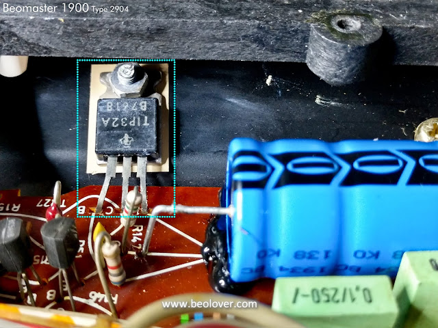
While working on the main board restoration I decided that I didn't like the looks of the way that the +15 VDC regulator device was mounted. The thermal past looked dried out and it would bother me to know that was in there like that.

I reworked the mounting of the regulator by cleaning off the old, dry paste and remounting the regulator with a SIL-Pad.


That looks better. Note that I also added some hot glue to help support the 2200uF capacitor for the +15 VDC supply.

One more change that I made to the main board was to replace the left and right channel 250Ω trimmers (for the output amplifiers' no load current adjustment) with new, sealed, multi-turn type trimmers.


That took care of the main board.
The Volume Control Board was next.

Here is the before photo.


Here is the after recapping photo.


This shows the Volume Control Board reinstalled.


So far the restoration work has meant the removal and replacement of sixty-four capacitors, two trimmers and the four diodes of the bridge rectifier.

This photo shows the removed parts.


I will have to do all of this again for the second Beomaster 1900 receiver.

There are still the tasks of the Tone Control/FM Tuner board recapping as well as the replacement of the Beomaster 1900 indicator lamps.  Once those tasks are complete I can start testing this receiver...the fun part.


Monday, January 18, 2021

Beogram 4002: Restoration of DC Platter Motor

Recently, I received a Beogram 4002 DC platter motor from California for restoration. This shows the motor: 
I took it apart to get to the bearings (the two small donuts on the black pad):

I submerged the bearings in motor oil and pulled a vacuum. Immediately, strong bubbling occurred: 
The bubbling indicates that the vacuum pulls the air from the pores of the bearing material. This makes room for oil to inter diffuse into the material. After about 72 hours the bubbling stopped and I extracted the bearings from the oil:
Then I reassembled the motor and installed it in one of my Beogram 4002s for a 24 hrs RPM stability test with my BeoloverRPM device. It measures the RPM in 10s intervals and transmits the data to any serial port:
This is the curve I measured:
This result is pretty much as good as it gets for a Beogram 4002 DC platter motor. This motor is ready for duty again!
 

Sunday, January 17, 2021

Beogram 4002: Restoration of DC Platter Motor

I recently received a Beogram 4002 DC platter motor from the Netherlands. Unfortunately, I was not able to restore it since someone had previously destroyed the top bearing suspension, which I was not able to bend back into a sufficiently precise shape.

Therefore, I restored a motor that I had available:

I disassembled the motor to extract the bearings for oil infusion:

I immersed the bearings in motor oil and pulled a vacuum. Immediately, vigorous bubbling started:

This indicates that air is being drawn from the pores of the bearing material, making room for oil to diffuse into the bearing. After about 48 hours the bubbling stopped and I extracted the bearings:
I reassembled the motor and installed it in one of my Beogram 4002s for an RPM stability test with the BeoloverRPM device:
After about 24 hours I had measured this curve:
This is pretty much as good as it gets with the Beogram 4002 DC motors, i.e. this motor is ready for duty again!