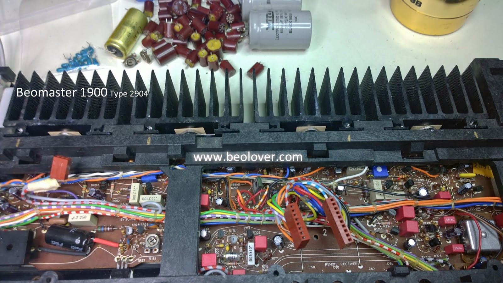
The restoration work on the main board and on the volume control board is now complete.
The Beomaster 1900 and 2400 receivers are low profile so they look small. I always start out these restorations thinking that it should be easy...but once I get started on the capacitor replacement I am quickly reminded at how many components there are.
Here is the main board as I received it.

Here is the main board after replacing the electrolytic and tantalum capacitors.

For capacitance values higher than 4.7uF I use high quality 105°C rated capacitors.

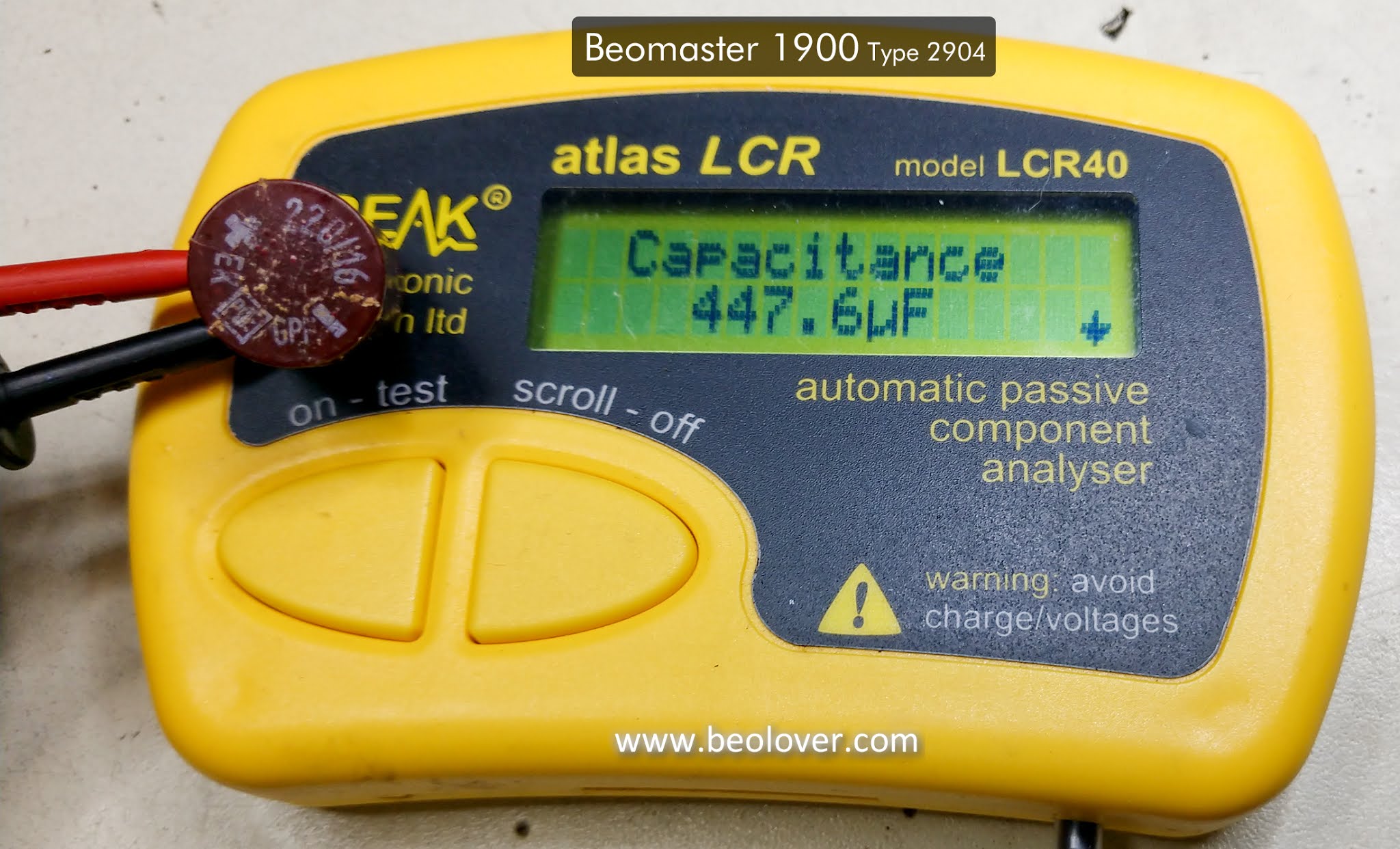


The two large reservoir capacitors for the output amplifier voltage rails are typically still within tolerance. The two on this Beomaster were as well but I replaced them anyway due to the effort it takes to change them out. I don't want to have to come back and do them later.

Here are the new ones.

While working on the main board restoration I decided that I didn't like the looks of the way that the +15 VDC regulator device was mounted. The thermal past looked dried out and it would bother me to know that was in there like that.
I reworked the mounting of the regulator by cleaning off the old, dry paste and remounting the regulator with a SIL-Pad.


That took care of the main board.
The Volume Control Board was next.
Here is the before photo.


So far the restoration work has meant the removal and replacement of sixty-four capacitors, two trimmers and the four diodes of the bridge rectifier.
This photo shows the removed parts.

I will have to do all of this again for the second Beomaster 1900 receiver.
There are still the tasks of the Tone Control/FM Tuner board recapping as well as the replacement of the Beomaster 1900 indicator lamps. Once those tasks are complete I can start testing this receiver...the fun part.