Featured Post

Beolover SyncDrive: DC Platter Motor Replacement for Beogram 4002 and 4004 (Type 551x and 552x)

Late Beogram 4002 and the 4004 (Types 551x and 552x), which have DC platter motors instead of the earlier synchronous AC motors usually suff...

Showing posts with label 2017JWBM1900. Show all posts

Sunday, December 3, 2017

Beomaster 1900 (Type 2903): New Program Function Lamps

With the replacement LEDs on the Bass, Treble and Balance indicators working out so well I decided to change the seven program function indicators to LEDs as well. They will just be a single LED component with a 1KΩ current limiting resistor.

I did one to test how the LED compares to the original incandescent lamp. The first lamp in the program selection group is the far left lamp - Phono.


Looking at the original lamp illumination on the Tape selection I have this


The new LED Phono lamp looks like this


That looks good to me so on with the other six lamps. As with all of our replacement components these LED plus resistor assemblies are drop in replacement for the original lamps. If someone wants to return to incandescent lamps in the future they can easily do that. However, these LED components look the same and run cooler.


Now to put everything back together and see how the Beomaster looks and works.


Very nice. Now let's look at it a little closer in.


I think this Beomaster 1900 project is very close to a wrap. Just another few days of testing are needed.

Tuesday, November 28, 2017

Beomaster 1900 (Type 2903): Installing The Replacement Slide Potentiometer Contact Bridges

I have been running the Beomaster 1900 with borrowed parts from a Beomaster 2400 until the contact bridge replacements for the slide potentiometers arrived from Denmark. Thanks to Martin Olsen they were sent right away and got here really quick.

Making the swap wasn't too bad. The board with the Bass, Treble and Balance slide potentiometers unplugs from the main board so it is easy to desolder the pots.

Here are the slide potentiometers and the replacement parts lined up for assembly.


The three black plastic pieces in the middle are the new contact bridges.


The replacement parts are just the plastic bridges. You must reuse the original contact components.
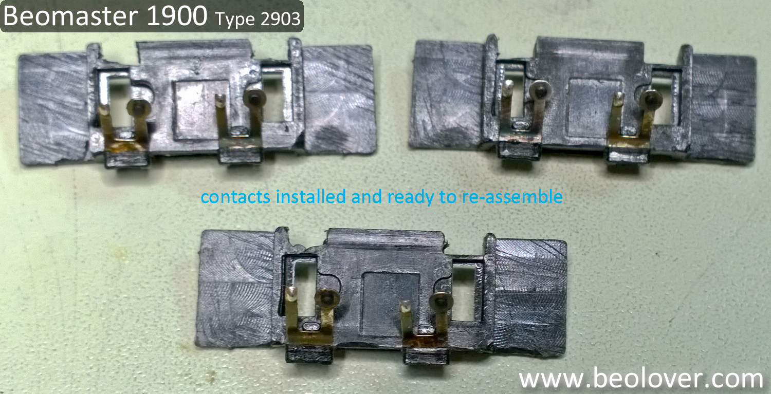
Here are the ones from this Beomaster installed in the bridges and then assembled into the slide potentiometers.


The bridges are not physically keyed so you could accidentally install them the wrong way. Make sure the bare contacts line up with the metal tracks. It is also important during the handling of the contacts to avoid disturbing the contact with the small, black coal piece.

Once the slide potentiometers are re-assembled their mounting holes to the board are keyed so the only thing to be careful with is that the 50KΩ potentiometer is placed in the Bass mounting location.


The rest of the task is just to snap and solder the potentiometers back into position on the removable board and remount it to the main board.


That is followed by a quick test play to make sure the reworked sliders function properly.


Note that I have the smoked glass display cover removed for polishing.

Saturday, November 25, 2017

Beomaster 1900 (Type 2903): Testing The New Bass, Treble and Balance Indicator Masks

The original display indicator masks for the bass, treble and balance settings on this Beomaster 1900 have deteriorated from long term exposure to the incandescent lamps. I measured up to 118°F on the tone control lamp lenses.


Since the bass, treble and balance lamps display their settings mechanically, by sliding the indicator mask across a fixed lamp source, these are a good case for switching from the hot, incandescent lamps to cooler operating LEDs.

Here is picture of the original incandescent lamps in their bare, illuminated state.


A design goal for a replacement lamp is to produce a reversible substitute part. The LED version of the lamp should just solder on to the same two board pads that the original lamps use. No modifications to the board should be necessary.
Each of the original lamps has a 68Ω current limiting resistor in series with it. For my replacement I decided to go with two LED devices and a load resistor to limit the current further and to control the illumination of the LEDs.

On my test circuit I used a 68Ω resistor (for the existing resistor in the Beomaster), two white LEDs and a 5KΩ trimmer resistor to come up with a good load resistor value. I ended up with a 1KΩ load resistor a and the results are a nice substitute for the original bulb. The illumination of the red indicator lens is nice and uniform.


My final replacement version of the LED assembly looks like this. I put clear heat shrink over the load resistor and color coded heat shrink to mark polarity of the LED (red for positive, black for negative).


Now for a quick test.


The test passes and showed me that I needed to bend the LED leads a little different in order to fit the lens cover assembly for the lamps.  Here is the board with all three replacement lamps in place.


The lens cover assembly fits back on and the new bass, treble and balance indicators are restored.
Before showing the new LED replacement lamps in action here is what the new indicator masks look like.


Here are the new bass, treble and balance indicators with the Beomaster 1900 turned on and playing.


The temperature on the indicator mask is much better now. These newly printed masks should last a long time.


Of course I will have to pull those three slider potentiometers again once Martin's new contact housings arrive. In the meantime I will put this Beomaster through a burn-in test. I will let the local classical radio station play for a few hours.


Thursday, November 16, 2017

Beomaster 1900 (Type 2903): Replacing The Bass, Treble and Balance Slider Potentiometers

Now that the Beomaster can power back up I performed the 15 volt supply check and adjusted the No-Signal Current setting for the left and right channels.


Since the left and right channel No-Load Current adjustment went smoothly I expected the Beomaster to be able to finally play music again. I used an ipod Nano as the source to the Beomaster Tape input and a pair of Beovox S55 speakers for the outputs. To my surprise I had no sound in the left channel. After some quick debugging I found that the Nano source signals were present in the Beomaster up to the balance slider. It is common for the bass, treble and balance slider potentiometers to develop problems in these receivers.

Checking the balance slider I found that it was the culprit.


Note: The tabs shown by the red arrows below have to be bent straight in order to disassembly the potentiometer.


I thought about doing a creative repair with some glue but figured there must be a better solution.
As it turns out, Martin at Beoworld makes a replacement part for the black slider housing that moves to change the output. That black slider housing is the piece with the broken tabs the potentiometer contacts are secured with. I ordered a set of three replacement parts as all three slider potentiometers (bass, treble and balance) have a broken contact mounting tab.

Since it will take at least a week for the parts to come from Denmark I wanted to keep going with the Beomaster restoration. I pulled the bass, treble and balance slider potentiometers from a Beomaster 2400. The Beomaster 2400 turned out to have nice, intact slider contact assemblies so they will do nicely and I have new assemblies on order. In the exchange of parts I will only take the contact assembly as the Beomaster 2400 Bass slider potentiometer is 20KΩ and the Beomaster 1900 Bass slider potentiometer is 50KΩ.


I cleaned the potentiometer contact strips and contacts with a fiberglass brush and some Deoxit Fader Lube.

With the Beomaster 1900 slider pots cleaned and rebuilt it was time to test the Beomaster 1900 for sound again.


Sly's voice came out beautifully on both Beovox S55 speakers. All of the slider potentiometers really needed that restoration.

Monday, November 13, 2017

Beomaster 1900 (Type 2903): Trying Out The Recapped Beomaster

I partially reassembled the Beomaster 1900 so I can check out my recap work and begin the amplifier adjustments. It is always an anxious moment when you first re-apply power having completely disassembled a unit.

This Beomaster powered right up to Standby mode and touching the FM5 terminal post put the receiver right into that mode (no FM antenna is connected yet). A great feeling for sure.


To get from the disassembled recapped boards to this first power on test I prepared the PCB 2 board for the No-Signal Current adjustment.

That adjustment will require measuring the voltage across the left and right channel emitter resistors while adjusting trimmers R259 and R359. I decided to install new trimmer resistors for those two devices. I didn't want to discover those old trimmers are a problem and have to remove PCB 2 again.
Here are the new adjustment trimmers installed.


The next step was to re-attach the four heat sinks for 2IC200/300 (TIP 141 Darlington pairs) and 2IC201/301 (TIP 146 Darlington pairs). The original mounting used thermal paste/adhesive to mount and insulate the transistors to the heat sink. For the re-assembly I decided to use a Thermalloy thermal interface product. It doesn't dry out like the paste and is less messy.


Tomorrow I will test the power supply voltages and do the No-Signal Current adjustments. Then I will see if I get output from the amplifier section.

Monday, November 6, 2017

Beomaster 1900 (Type 2903): Recapping the Boards

Replacing the old electrolytic and tantalum capacitors on these low profile Beomaster receivers can be time consuming as everything is very compact inside.

The first board I recapped was the Tone Control & Tuning board (PCB 4) as it was the easiest to get to.

Before


After


Next up are the Volume Control board (PCB 3) and the Mains board (PCB 8).

Before


After


Before


After

The most time consuming tasks were on the IF Section, Decoder, Program Selection & AF Amplifier board (PCB 2) because of the number of capacitors to replace. The two 5000uF reservoir capacitors are also a bit of a pain to change. There are a lot of wires that solder onto the capacitor terminals which make for some congested soldering.

Here is PCB 2 prior to recapping it.


Here is PCB 2 after the recap. You can see the pile of old capacitors. I always measure all of the capacitors I remove. On this receiver most of the the old electrolytic capacitors measure out of tolerance. A few were dead.  So the recap was badly needed on this Beomaster.


On the reservoir capacitors I decided to use a heavy duty connector to consolidate all of the wires that need to connect to the two capacitors. This allowed me to only have to solder three wires to the actual reservoir capacitors. Much easier to manage.

Before


After


There is one 10uF, 10V tantalum capacitor inside the metal box that holds the Front End, Tuner board (PCB 1).

Before


After


Here is another picture of the recapped PCB 1, 2, 3 and 4 boards.