Featured Post

Beolover SyncDrive: DC Platter Motor Replacement for Beogram 4002 and 4004 (Type 551x and 552x)

Late Beogram 4002 and the 4004 (Types 551x and 552x), which have DC platter motors instead of the earlier synchronous AC motors usually suff...

Showing posts with label WIMA. Show all posts

Sunday, July 13, 2025

Michigan Beogram 8002 Electronic Restoration

The electronic restoration process for the Beogram 8002 mainly involves the two circuit boards, PCB 1 - PCB 2, the Beogram transformer module and the control button panel.

Here are PCB 1 and PCB 2.


Starting with PCB 1, here is a survey of the capacitors that will be replaced.


Pretty straight forward but I always like to pull the base off the old C27 capacitor (2200uF, 40V) and re-use it on my replacement capacitor.  The three-pronged base of the capacitor provides good support on the circuit board and is the negative terminal of the capacitor...so it is very handy to re-use on my replacement cap.


Here is a survey of the PCB 1 capacitors after I replaced them.  I like to replace all of the electrolytic capacitors 4.7uF and smaller with WIMA MKS, non-polarized capacitors (the red ones in the photo).


Next is the PCB 2 assembly.  It houses the microcomputer IC (a 40-pin device).  There is just one electrolytic capacitor on this board and it is for the +5 VDC power required for the uC device.  In this case, the capacitor is blown as seen in the photo below.


On the restoration for this board I remove the uC device first so I can replace the 40-pin socket with a newer one.  While the C1 capacitor is better exposed I replace it.


Now the Beogram 8002 uC device is re-installed.

REMINDER: Always take electrostatic protection precautions when handling sensitive electronic components such as digital integrated circuit devices.

Also, re-inserting a 40-pin device into a socket is not as easy as you might think.
The pins will never line up perfectly and care must be taken not to accidentally bend a pin while getting them all in place.


There is a lone control wire for the uC reset signal from PCB 2 that attaches to a terminal post on PCB 1.
The wire is a small gauge, shielded wire that often breaks where it solders onto the connector for the terminal post.  

That was the case on this Beogram 8002 so I added some extra support when I re-installed the wire.


PCB 1 and PCB 2 are now complete.  I will wait to re-attach the PCB 2 top lid until I do some Beogram 8002 functional testing. 


The electrolytic capacitor inside the Beogram 8002 transformer assembly is a non-polar capacitor that the Beogram requires for the platter motor to turn.  It is the starting phase capacitor and since it didn't fit on PCB 1, the engineers located it in the transformer compartment.

The value of the phase capacitor is different for different line frequencies.  In the US, where the line voltage is at 60 Hz, the Beogram 8002 phase capacitor is 27uF.


The Beogram 8002 Control Panel doesn't have any capacitors to replace but I do like to take it apart for cleaning, checking and installing a little test connector.

This Control Panel is in very nice condition.

The black plastic tabs in the photo that attached the PCB to the Control Panel frame are often broken (Who knows why).

These are all accounted for.

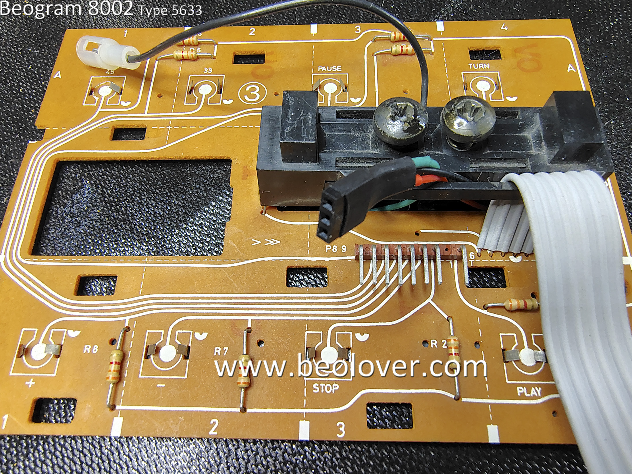
The highlighted module in the photo is where a single lamp and two LDR devices live.
The two large screws adjust the amount of light that passes from the lamp to each LDR.
This mechanism sets the idle voltage control for the Beogram 8002 servo motor that moves the tangential arm assembly.  The B&O service manual says to set the screws so the Forward and Reverse scanning functions are at an idle voltage level of 620mV.

These voltages feed into the positive input of the Op-amps controlling the tangential arm servo motor.
The 620mV level is the input level for the Forward and Reverse controls where they are not driving the motor forward or reverse.

When someone is pressing down on the Forward or Reverse scanning buttons a spring loaded aperture allows more light to the LDR and sends a higher voltage to the servo motor control to move the arm assembly forward (or backwards).

The adjustment of these scanning function screws is always a pain for me.
To set the 620mV level the LDR is measured to ground.
There are no convenient test points provided on the control panel and there have been times when I have wanted to check the LDR levels without completely opening up the Beogram.

For that reason I always install a little test connector that is accessible by pulling off the Control Panel.
That way the measurement and adjustment can be made at any time later.

Here are some photos to demonstrate....


The underneath side of the Control Panel is much cleaner than other Beogram 8002 units I have worked on. Very nice.


Here are my three test wires for measuring the two LDR devices.


...and here is the test connector installed and ready to use.


Everything is now complete where I can do a quick test to see if the Beogram 8002 comes to life.

I assembled all of the components on my bench with the floating chassis and plugged the Beogram 8002 in to AC power.


Happily I got the red dot on the display indicating "standby" and I observed the little wiggle of the platter as power is applied to the system.
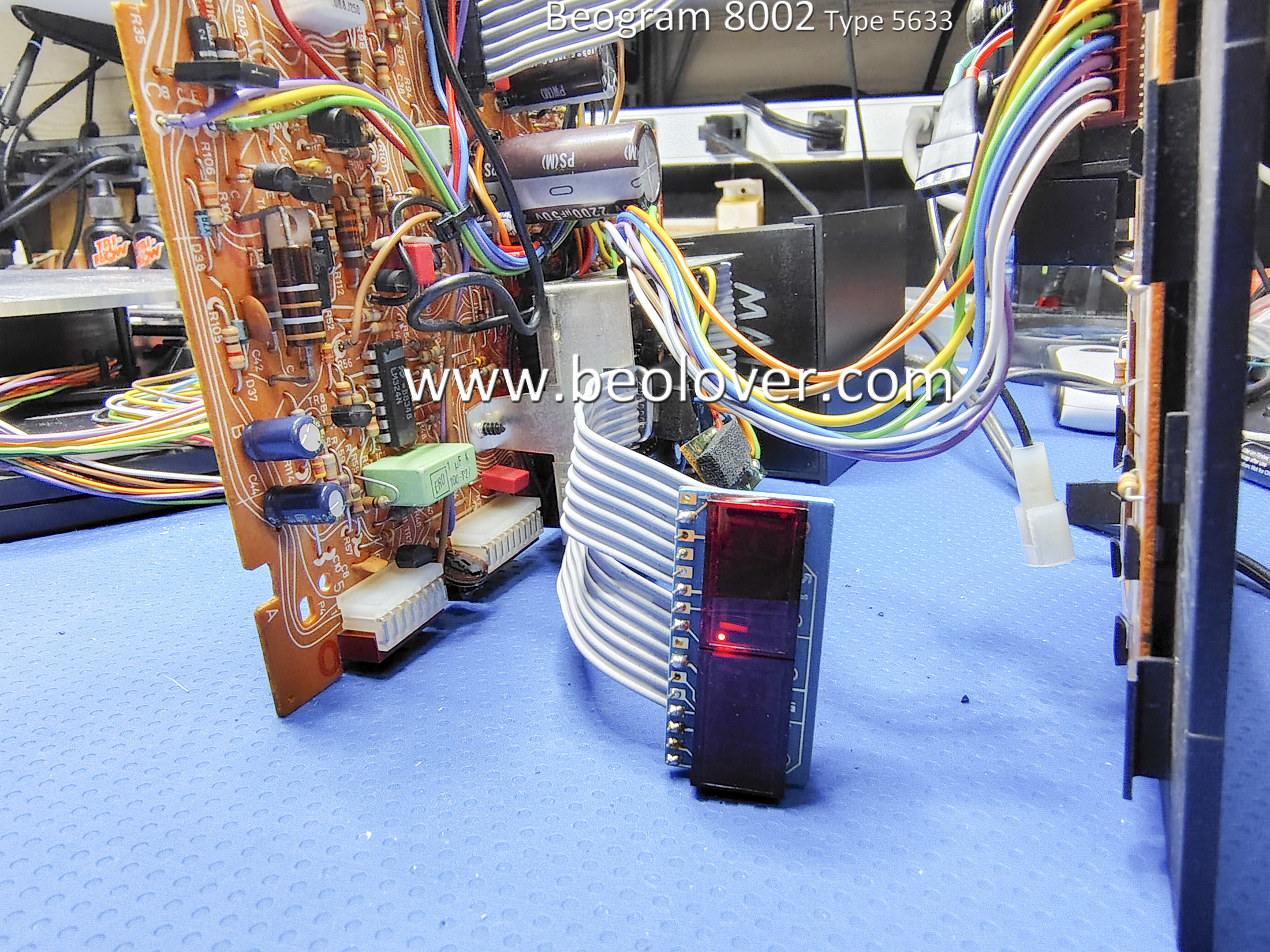


The platter turn functions worked with both 33.33 and 45 RPM speeds able to lock in as expected.

I pressed Play and the Beogram arm assembly moved forward...Then it stopped moving.

That isn't totally unexpected during a "first power on" test.  It usually means there is a problem with the scanning LDR assembly in the Control Panel that I mentioned earlier.

Time to connect up my handy test connector and measure the LDRs.


Sure enough, the voltages for the scanning LDR devices were well over 1 V.  Too high over the 620mV level they should be at.  Of course this messes with the Beogram servo control circuit and the arm tends to stop.

I was able to adjust the LDR voltages to a level where the Beogram would operate but it was with the LDR voltage steady-state values of around 800mV.  However, that was with the adjustment screws fully opened up.

That isn't a good long term solution so I will have to return to the Control Panel assembly and do some work on the LDR devices. 

I want the LDR voltage levels to be around the 620mV idle voltage level with plenty of room for adjustment of the adjusting screws.

Monday, October 8, 2018

Canada Beomaster 8000: Final four capacitors replaced

There are just four remaining capacitors to replace on the Beomaster 8000 from Canada. Two capacitors each on the microcomputer board and the display board.

The microcomputer board on this Beomaster is about as pristine as you will find. No need for any board cleaning on this beauty.


The two capacitors to replace on this board are inside the metal shield box. There is a top piece to the shield box (shown above) and a bottom piece shown here.


The inside of the bottom cover has a paper insulator to keep the metal cover from shorting component leads.

Here is the inside of the box (front and rear)


I will say it again...this board is in beautiful condition. The two capacitors to change out are a 1uF and a 22uF capacitor.


I am only doing the two capacitors on this board for now. I want to check the Beomaster 8000 power supply so I will re-install this recapped microcomputer board for that test. Once the power supply test is verified I will come back to this board and change the two oscillators as well as reflow a number of solder joints.


I will do a similar thing with this Beomaster's display board.  For now I will just change out two capacitors on that board but will return to it later for the restoration of the segmented displays, replacing the four incandescent lamps and reflowing solder joints.

Here is the display board as I received it.


The two capacitors are easy to get to so I quickly changed them out.


Here is the completed board.


Saturday, February 3, 2018

Beomaster 6000 (2702) restoration: recapping level amplifier with SQ decoder and pre-amplifier

When restoring vintage audio equipment it is good practice to replace all electrolyte and tantalum capacitors. Today the level and pre-amplifier PCB's are done as well as the small PCB for the SQ decoder that plugs into the level amplifier. This was done to allow further upgrade to new quadrophonic (de)coding systems. There was no standard yet in the mid seventies and in fact there really never came a standard! During those days about a dozen systems existed. Some for records, some specific for tape: SQ, CD-4 (used in the Beogram 6000), QS, DY, EV, UD-4, Quad-8, Q4 (the very first - invented in the fifties), etc. None was really successful and all where abandoned a decade or so later.

Today we would probably call this quadro systems: 4.0 surround sound !

Anyhow, back to the recapping. When replacing capacitors it is obvious that the value and voltage rating is crucial and need to match. Sometimes two or more capacitors need to be combined (in series or parallel) to match the old one. It is common in speaker crossovers for example to see odd values that are no longer industry standard.

But dealing with recapping of PCB's in this Beomaster 6000 quad poses another challenge: box size ! On the pre and level amplifier there are more than 60 capacitors and mostly tantalum. They where chosen for the small size compared to the aluminium electrolytes for the same values (today electrolytes are a lot smaller than back in those days). But even today, when replacing those tiny tantalum's, it is often impossible to go for electrolytes because they simply don't fit in the space. The WIMA MKS foil capacitors are the best choice for me. But even then, one needs to be very careful what type is chosen. Don't go to high in max voltage rating, check the different box sizes between the different PCM measures (2,5 or 5mm distance between the leads). Some are square, some are rectangle. Many of the MKS (polyester film types) that I had in stock did not fit. 

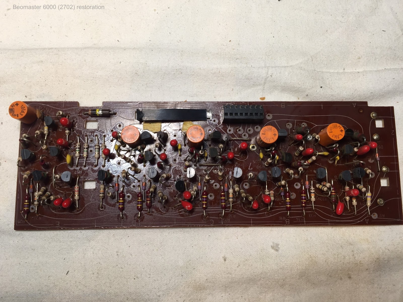
This is for example the level amplifier before recapping


And after recapping


And the SQ decoder that fits in the black plug in the above PCB


The pre-amplifier was even more challenging


Only a few boards left now for recapping. But that is for a next post...

Monday, November 6, 2017

Beomaster 1900 (Type 2903): Recapping the Boards

Replacing the old electrolytic and tantalum capacitors on these low profile Beomaster receivers can be time consuming as everything is very compact inside.

The first board I recapped was the Tone Control & Tuning board (PCB 4) as it was the easiest to get to.

Before


After


Next up are the Volume Control board (PCB 3) and the Mains board (PCB 8).

Before


After


Before


After

The most time consuming tasks were on the IF Section, Decoder, Program Selection & AF Amplifier board (PCB 2) because of the number of capacitors to replace. The two 5000uF reservoir capacitors are also a bit of a pain to change. There are a lot of wires that solder onto the capacitor terminals which make for some congested soldering.

Here is PCB 2 prior to recapping it.


Here is PCB 2 after the recap. You can see the pile of old capacitors. I always measure all of the capacitors I remove. On this receiver most of the the old electrolytic capacitors measure out of tolerance. A few were dead.  So the recap was badly needed on this Beomaster.


On the reservoir capacitors I decided to use a heavy duty connector to consolidate all of the wires that need to connect to the two capacitors. This allowed me to only have to solder three wires to the actual reservoir capacitors. Much easier to manage.

Before


After


There is one 10uF, 10V tantalum capacitor inside the metal box that holds the Front End, Tuner board (PCB 1).

Before


After


Here is another picture of the recapped PCB 1, 2, 3 and 4 boards.


Thursday, July 13, 2017

Beogram 4004 Type 5526: Output Board Recap and Update

The Beogram 4004 output board has the usual phono signal connector and muting relay but also has circuitry added to allow remote control functionality from a Beomaster such as the Beomaster 2400. For this board I replaced the two electrolytic capacitors with new ones and the two tantalum capacitors with WIMA MKS capacitors. I replaced the muting relay with a new, sealed Omron relay mounted on Beolover's custom adapter (so that it is directly replaceable with the original National relay).


As Beolover typically does I added an optional phono cable grounding switch to the output connector. This switch allows an owner to connect the phono signal shield wires to the Beogram chassis ground or leave them open (as they normally are). The normal configuration is fine when using the Beogram phono DIN connector with a B&O Beomaster (like the 2400). However, when connecting the phono cable to a non-B&O amplifier there is often hum present that requires connecting an extra grounding wire from the Beogram to the amplifier chassis ground lug. This grounding switch eliminates the need for the extra grounding wire.

While the small switch is secured by the leads soldered to the board, I added black hot glue around it to give it extra support. I like that glue for this application because it will provide the needed support but isn't permanent like epoxy glue. The black hot glue can be peeled off in the future if so desired.


This board is a quick task so it is on to turntable mechanical parts for cleaning, lubrication and adjustment.

Monday, July 10, 2017

Beogram 4004 Type 5526: Starting the Restoration

Just like the Beogram 4002 turntable restoration I recently did, this Beogram has a bunch of debris inside from the disintegrated plastic transport bushings. Due to continuously finding pieces during the Beogram 4002 project I decided to start off with the debris cleanup on this Beogram 4004.


Every nook and cranny has some piece of debris in it.


Even the tangential arm assembly didn't escape the spread of the bushing debris.


Eventually I got everything cleaned up.


Next I decided to start in on the electrical restoration. The first thing is the power reservoir capacitor that mounts to the chassis. I am replacing the original 4000uF capacitor with a Beolover replacement that includes a 3D printed housing so it can mount with the capacitor mounting bracket.


The custom part makes this installation a breeze and professional.

Now for the Beogram 4004 main board. It has a lot of blue tantalum capacitors that need replacing and a few electrolytic capacitors I will also replace. For values 4.7uF and less I like using WIMA polyester capacitors. They are non-polar and last a long time. In a couple places where the larger 4.7uF WIMA capacitors don't fit, I will use Nichicon 4.7uF electrolytic capacitors.

This board will also get three trimmer resistors replaced: the 33 RPM adjustment trimmer, the 45 RPM adjustment trimmer and the calibration trimmer for the photo darlington adjustment. That is the sensor for the tangential arm transport position.

I will also replace the RPM speed select relay with a Beolover custom replacement relay module.

Here is the main board prior to the restoration work.


These next pictures show the new Beolover RPM relay and the trimmers that were replaced.


Here is the finished main board.


Next up is the small output board.