The electronic restoration process for the Beogram 8002 mainly involves the two circuit boards, PCB 1 - PCB 2, the Beogram transformer module and the control button panel.
Here are PCB 1 and PCB 2.

Starting with PCB 1, here is a survey of the capacitors that will be replaced.

Pretty straight forward but I always like to pull the base off the old C27 capacitor (2200uF, 40V) and re-use it on my replacement capacitor. The three-pronged base of the capacitor provides good support on the circuit board and is the negative terminal of the capacitor...so it is very handy to re-use on my replacement cap.

Here is a survey of the PCB 1 capacitors after I replaced them. I like to replace all of the electrolytic capacitors 4.7uF and smaller with WIMA MKS, non-polarized capacitors (the red ones in the photo).

Next is the PCB 2 assembly. It houses the microcomputer IC (a 40-pin device). There is just one electrolytic capacitor on this board and it is for the +5 VDC power required for the uC device. In this case, the capacitor is blown as seen in the photo below.

On the restoration for this board I remove the uC device first so I can replace the 40-pin socket with a newer one. While the C1 capacitor is better exposed I replace it.


Now the Beogram 8002 uC device is re-installed.
REMINDER: Always take electrostatic protection precautions when handling sensitive electronic components such as digital integrated circuit devices.
Also, re-inserting a 40-pin device into a socket is not as easy as you might think.
The pins will never line up perfectly and care must be taken not to accidentally bend a pin while getting them all in place.

There is a lone control wire for the uC reset signal from PCB 2 that attaches to a terminal post on PCB 1.
The wire is a small gauge, shielded wire that often breaks where it solders onto the connector for the terminal post.
That was the case on this Beogram 8002 so I added some extra support when I re-installed the wire.

PCB 1 and PCB 2 are now complete. I will wait to re-attach the PCB 2 top lid until I do some Beogram 8002 functional testing.

The electrolytic capacitor inside the Beogram 8002 transformer assembly is a non-polar capacitor that the Beogram requires for the platter motor to turn. It is the starting phase capacitor and since it didn't fit on PCB 1, the engineers located it in the transformer compartment.
The value of the phase capacitor is different for different line frequencies. In the US, where the line voltage is at 60 Hz, the Beogram 8002 phase capacitor is 27uF.
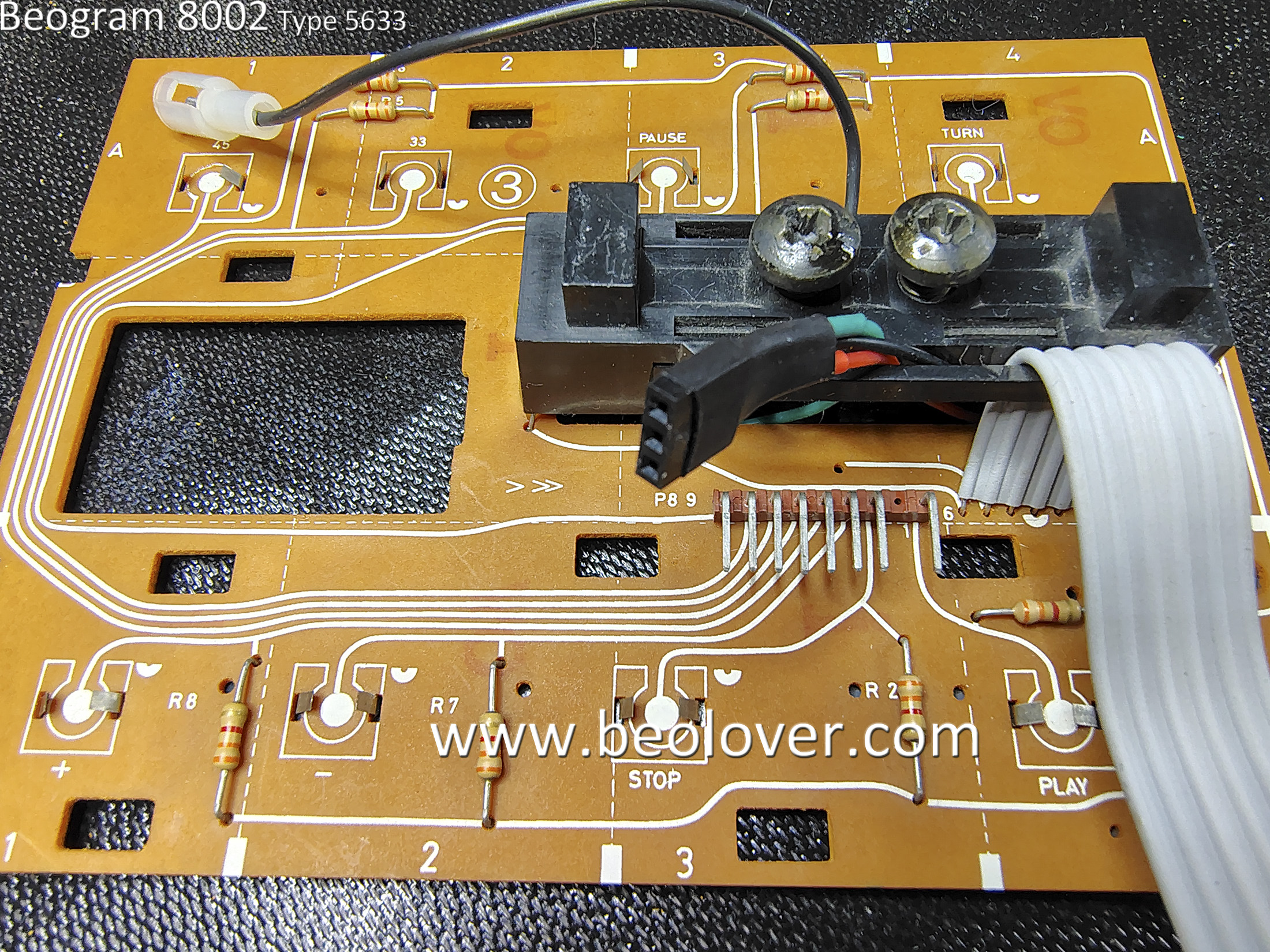
The Beogram 8002 Control Panel doesn't have any capacitors to replace but I do like to take it apart for cleaning, checking and installing a little test connector.
This Control Panel is in very nice condition.
The black plastic tabs in the photo that attached the PCB to the Control Panel frame are often broken (Who knows why).
These are all accounted for.
The highlighted module in the photo is where a single lamp and two LDR devices live.
The two large screws adjust the amount of light that passes from the lamp to each LDR.
This mechanism sets the idle voltage control for the Beogram 8002 servo motor that moves the tangential arm assembly. The B&O service manual says to set the screws so the Forward and Reverse scanning functions are at an idle voltage level of 620mV.
These voltages feed into the positive input of the Op-amps controlling the tangential arm servo motor.
The 620mV level is the input level for the Forward and Reverse controls where they are not driving the motor forward or reverse.
When someone is pressing down on the Forward or Reverse scanning buttons a spring loaded aperture allows more light to the LDR and sends a higher voltage to the servo motor control to move the arm assembly forward (or backwards).
The adjustment of these scanning function screws is always a pain for me.
To set the 620mV level the LDR is measured to ground.
There are no convenient test points provided on the control panel and there have been times when I have wanted to check the LDR levels without completely opening up the Beogram.
For that reason I always install a little test connector that is accessible by pulling off the Control Panel.
That way the measurement and adjustment can be made at any time later.
Here are some photos to demonstrate....

The underneath side of the Control Panel is much cleaner than other Beogram 8002 units I have worked on. Very nice.

Here are my three test wires for measuring the two LDR devices.

...and here is the test connector installed and ready to use.
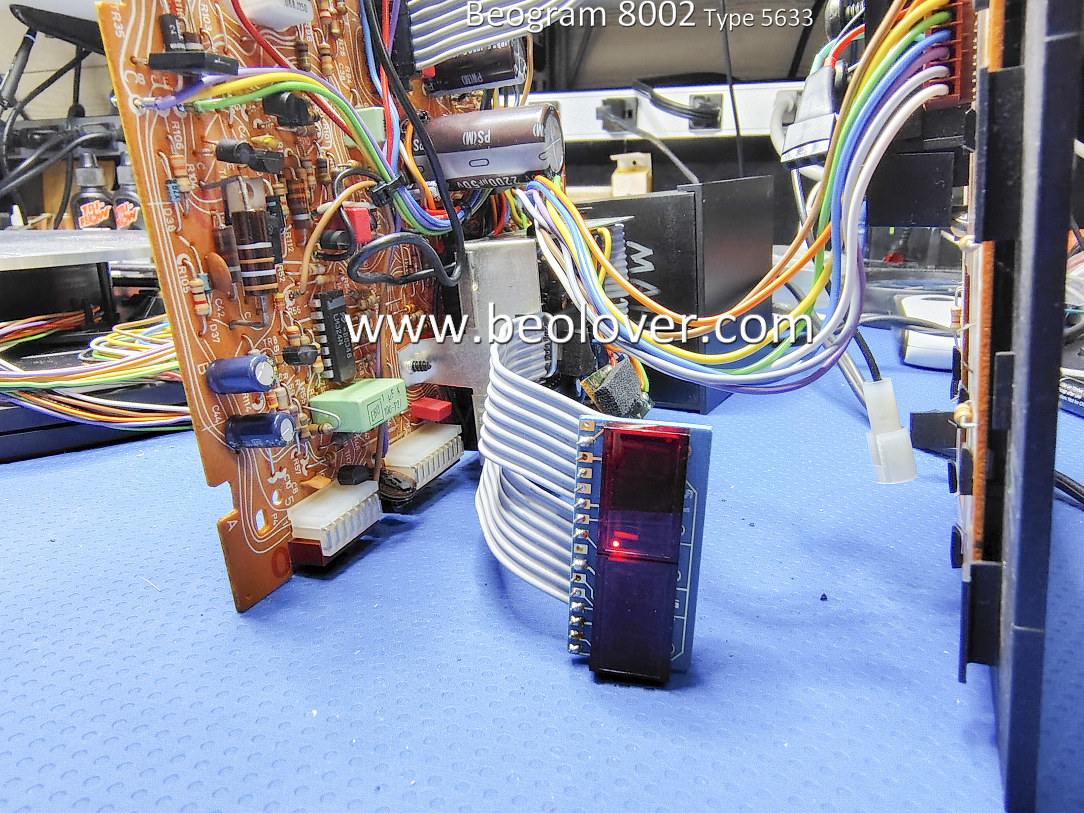
Everything is now complete where I can do a quick test to see if the Beogram 8002 comes to life.
I assembled all of the components on my bench with the floating chassis and plugged the Beogram 8002 in to AC power.

Happily I got the red dot on the display indicating "standby" and I observed the little wiggle of the platter as power is applied to the system.
The platter turn functions worked with both 33.33 and 45 RPM speeds able to lock in as expected.
I pressed Play and the Beogram arm assembly moved forward...Then it stopped moving.
That isn't totally unexpected during a "first power on" test. It usually means there is a problem with the scanning LDR assembly in the Control Panel that I mentioned earlier.
Time to connect up my handy test connector and measure the LDRs.

Sure enough, the voltages for the scanning LDR devices were well over 1 V. Too high over the 620mV level they should be at. Of course this messes with the Beogram servo control circuit and the arm tends to stop.
I was able to adjust the LDR voltages to a level where the Beogram would operate but it was with the LDR voltage steady-state values of around 800mV. However, that was with the adjustment screws fully opened up.
That isn't a good long term solution so I will have to return to the Control Panel assembly and do some work on the LDR devices.
I want the LDR voltage levels to be around the 620mV idle voltage level with plenty of room for adjustment of the adjusting screws.
No comments:
Post a Comment
Comments and suggestions are welcome!