This post describes the functional restoration of a Beogram 8002 that I recently received from a customer in Massachusetts. My initial assessment of this unit is posted here.
For working on a Beogram 8002 it is best to completely remove all functional components from the enclosure and plug them back together on the bench. I like to do it on a 'Lazy Susan' so one can rotate the fragile setup without pulling wires too much:

As usual with the 8002 I started my restoration process with rebuilding the board. It is easily extracted by unplugging all the wire harnesses and the transformer block:

I removed the microprocessor can:

I could not help noticing that the single wire that makes a connection to the main PCB had broken off from the solder tab:

I re-soldered the connection and secured it with a bit of shrink tubing:

Then I replaced all the electrolytic capacitors:

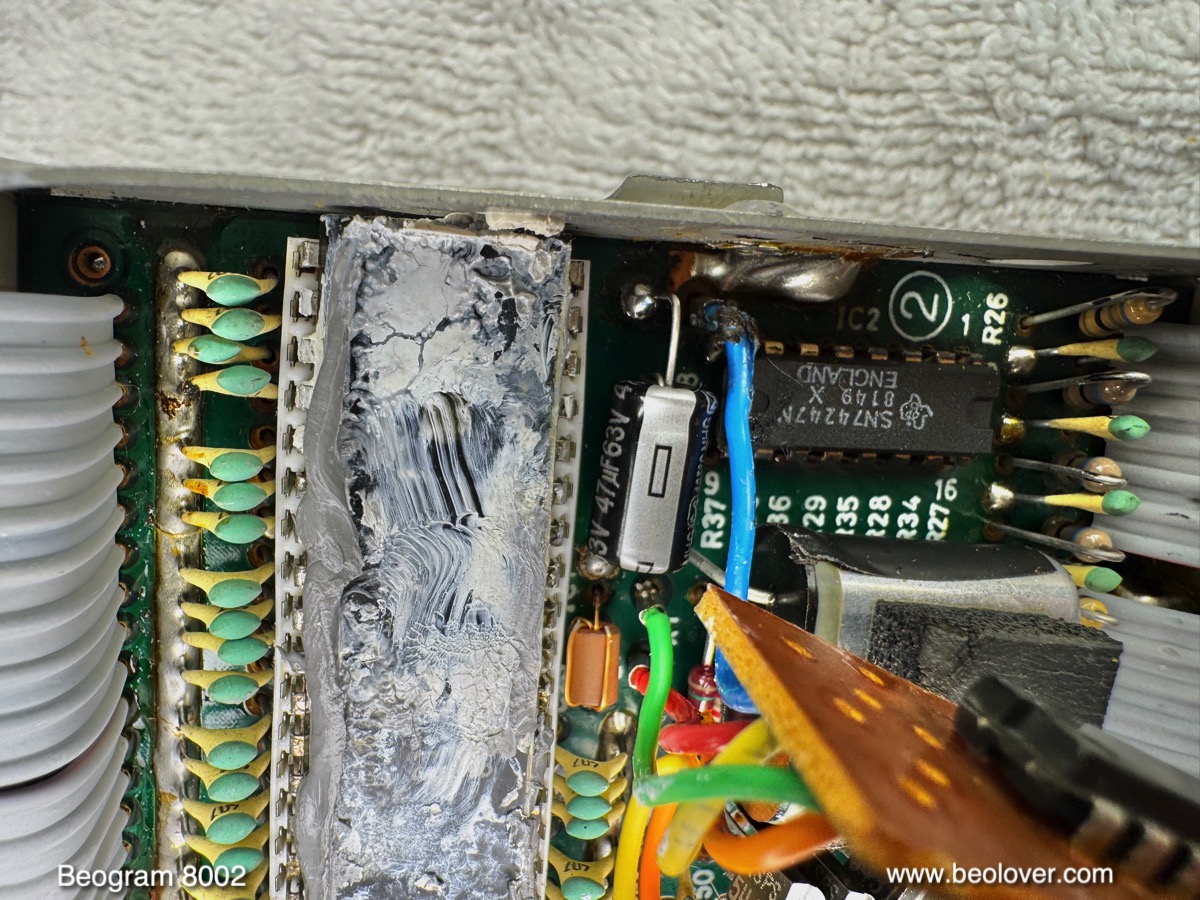
Next came the decoupling capacitor in the microprocessor can:

I opened it up on both sides. This shows the component side of the board inside:

The capacitor is under the small piggybacked board:

The shield connection of the wire that was broken off on the other end had come loose inside the can:

I cleaned up the mess

and secured everything with shrink tubing:

Then I implated a new capacitor from the top side:
It is important to know that one of the leads of this capacitor also serves as a "1980s style" (;-) board via and must be soldered on both sides of the board.
I closed the microprocessor can up again and re-installed it on the main PCB:

Then I had a look inside the transformer block. I found a fuse attached to the big motor phase shift capacitor:

The fuse that was in the fuse holder was burned out:

I replaced the fuse with a new one and then removed motor capacitor, which I replaced with a new Beolover Motor Capacitor for Beogram 8000 and 8002:

This component is a modern take on the original non-polar electrolytic unit. I designed it with ceramic capacitors that are 'naturally' non-polar. A much better and durable choice than the original capacitor the basically contains two back to back connected standard polar electrolytic capacitors of double capacitance (hence the large size). My replacement part also can be used both for US 60 Hz as well as European 50 Hz Beograms by simply selecting the correct capacitance when connecting the wires.
There are a couple more electrolytic capacitors that need replacing. They are directly connected to the 5V voltage regulator that is clamped to the bottom plate of the enclosure for heat dissipation. This shows the setup as I found it:

Sadly, a couple wires had damaged insulation from previous repair efforts:

I secured the damaged wires with some shrink tubing and I installed fresh capacitors:

Then I plugged the unit in. The keypad was completely dead and there was also no dot in the 7-segment display. But light came from the tracking sensor housing:

This indicated to me that there was most likely a problem with the 5V power rail. I traced the 5V rail from the 5V regulator to the board and and then to P6 that makes all the connections to the microcontroller can. At pin 1 of this connector I measured 0.45V instead of 5V:

This indicated that there was some unwanted resistance on the way to this pin. Indeed after going solder-point-to-solder-point with my multimeter I found a poorly repaired cracked solder point. I cleaned up the mess and soldered a wire across the damaged traces:

This restored the power connection and the deck came alive and showed the normal illuminated decimal point in the 7-segment display. I pressed start and the carriage started moving. Very good signs indeed!
Now it was time to clean the mechanical parts and lubricate them with modern synthetic lubricants. I removed the rods on which the carriage travels, as well as the threaded spindle. This liberated the carriage:

which gave me access to the screw that allows adjusting the vertical alignment of the tone arm. I adjusted it parallel to the sensor arm. This shows the carriage parts as extracted:

Lots of teflon grease! Not sure why I find so much teflon grease in Beograms when I restore them. In my opinion it is the least suitable lubricant for these delicate devices!
Luckily there are ultrasonic cleaners that can clean such messes quickly! This shows the nice and shiny parts after the clean:

I also cleaned the teflon mess from the underside of the carriage:

And then I reassembled everything:

I also installed a new Beolover Carriage Belt for Beogram 8000 and 8002:

It is a good idea also replacing the output relay. They are often oxidized. This shows the setup inside the DIN7 jack assembly. The relay is under the clamped on cover:

I pried the cover off with a screwdriver, which revealed the original relay:

I implanted a new modern encapsulated Output Relay for Beogram 8002:

The new relay has a similar width like the original one and the shield still fits as before:

The Beogram 8002 often has hum issues when it is connected to phono inputs of amplifiers. Connecting system and signal grounds normally quenches the hum. I usually install a switch (red) that allows easily making this connection when necessary:

The next step was replacing the light bulb in the << and >> buttons assembly. The Beogram 8000/8002 models have a nifty mechanism that allows variation of scanning speed of the carriage depending on how strongly the buttons are pressed. This functionality is achieved by a mechanism where the buttons drive apertures into the light path between a bulb and photo resistors. The less light falls on the resistors the faster the carriage moves. This setup is inside the black box on the backside of the keypad:

In order to be able to work on this the PCB has to be removed from the actual keypad. Unfortunately, the person working on this Beogram before me did not seem to know that the board can slide out to the side, and so a couple of the flimsy plastic clips broke off during his "learning process" and correction was attempted by using some gunky adhesive. Not very Beolovely:

I cleaned up the mess as best as I could and slid the keypad out. Then I removed the plastic cover. This revealed the light bulb and the photo sensors. The button-activated apertures are the metal strips right in front of the photo resistors:

I removed the bulb and prepared a white 5 mm LED by sanding it a bit to ensure even diffusion of the light. I also Dremeled the bottom lip off since the bulb is exactly 5 mm, while the lip on such LEDs is a bit wider than that:

This shows the LED installed:

On the backside of the PCB the current limiting resistor is visible:

It is important that it is installed in about this location. Otherwise it will interfere with sliding the PCB back onto the keypad. I re-assembled the keypad and plugged it back in and started the Beogram. After 5 min runtime, I measured the photoresistor voltages and adjusted the light intensity controlling screws in the black housing to get the manual-specified 620mV:

This is an important adjustment since the circuit uses this voltage to decide whether to lift the arm or keep playing.
After the adjustment I restored one of the cracked but still dangling plastic tabs on the back of the keypad with a dab of epoxy. I also restored the threads of the small screw that secures the PCB in place with some more epoxy:

And then it was time to enjoy this functionally restored Beogram 8002 with a first record! I selected a vinyl I recently bought: "After Hours" by Manfredo Fest. He recorded this wonderful album in 1972 for Daybreak Records. I read it was his first foray into the US market after already having made a name for himself in Brazil. Of course this album was ultrasonically cleaned on a CleanerVinyl ProXL setup before listening!
This shows the Beogram playing the record:

I will now play the unit for a while and if nothing else comes up it will be time to put it back into its enclosure and send it back to its owner.
Update after ~three weeks playing around 50 albums on this Beogram:
Everything seems to be working perfectly and I was not able to find any intermittent issues. So I put it back into its enclosure and played it a bit more. Here a nice photo together with a recent Blue Note re-issue of Horace Silver's "Serenade to a Soul Sister". One of my favorite and hard to find albums and when they recently re-issued it I immediately ordered it. Beolovely!:

No comments:
Post a Comment
Comments and suggestions are welcome!