Featured Post

Beogram Commander Remote Control: Maybe This is the Final Version!..;-)

This is a follow up to my recent post about the redesigned Beogram Commander remote control board, which now works in both (DC-motor) Beogr...

Sunday, January 31, 2016

Beogram 4002 (5503): Restoration of Tracking and Tonearm Lowering Systems:

When I restore a Beogram 4002 I always start with the tracking and arm lowering systems, since they are essential for further diagnosis and operation of the turntable. So I went there first with this 5503 type, too. I started with the arm lowering mechanism. Here is a picture of the mechanism:

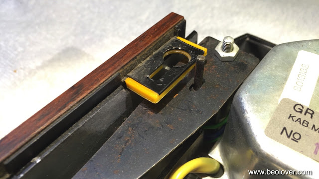
An interesting detail of the 5503 setup is the solenoid current limiting, which is implemented with a limit switch actuated by a plastic extension attached to the solenoid linkage:
The later DC motor models use an electronic limiting circuit based on a RC delay. This is much more similar to what is found in the original Beogram 4000 models, where a simple leaf contact is used to accomplish this task. The limit switch is definitely a better way to do it. But of course the electronic mechanism is superior to both switch based solution as it not uses mechanical parts.

And after taking out all moving parts except the solenoid. I usually leave it in but give the plunger a dab of silicone grease and work it in.
This are the parts spread out on the bench:
After cleaning the sleeve bearings of the arms and the damper interior with some mineral spirits, I lubricated everything and put it back together. This video shows how to rebuild the tone arm mechanism in detail. I usually adjust the damper when I adjust the tracking system feedback sensitivity since at that point one needs to lower the arm. The next step was lubricating the connecting linkage between damper and tonearm. I took out the sensor arm assembly
and then extracted the linkage for cleaning and lubrication:
This video shows how to get to the damper to arm linkage and re-lubricate it. After I put it back in it turned out that the arms were misaligned. The retaining washer on the connecting linkage was set too loose, which had the consequence that the linkage was not fully pressed against the sensor arm mount. If the arm parallelism is adjusted in this condition, the adjustment is not stable. This is how it looked after I put the sensor arm assembly back in:
Shifting the linkage at the back of the tonearm counterweight set things straight:
After this it was time for the tracking system. This shows the original setup with the incandescent light source installed:
I usually put in a SMD LED based light source in the tracking sensor to make sure it will last for a long time. This is only a small additional effort since the system needs to be adjusted anyway to bring the Beogram up to specifications. The intensity trimmer that is integrated into my replacement part also makes it very straight forward to fine adjust the sensor feedback sensitivity. A great upgrade to consider if you rebuild your own 4002! This part is available. Just send me an email.
This shows it installed:
After that it was time for my least favorite record (free jazz by Sam River) and my dented MMC20EN cartridge to do the tracking system feedback sensitivity adjustment. The goal is to adjust the system that the carriage starts moving after two-three full turns of the record when the needle is lowered on the record.
First, a coarse adjustment is done with the excenter on the base of the sensor assembly:
Once the sensitivity is close to the prescribed 2-3 turns, fine adjustment is done with the integrated intensity trimmer:
After that the mechanism was almost ready for prime time. There is a video that shows the tracking sensor adjustment procedure in detail. Still annoying was the wobbling cracked carriage pulley that caused un-Beolovely vibration during fast carriage movement. Someone previously glued it back together and (nastily) also onto the spindle shaft
I replaced it with a precision aluminum pulley provided by Nick of Beoworld (feel free to send me an email if you want me to put you in touch with him to get your own pulley):
Here is a photo of the installed pulley with a new belt:
I just love how this pulley looks! It elevates the entire mechanism to a much more precise feel. After installing the pulley I cleaned the spindle from hardened lubricants with mineral spirits and then lubricated it with some silicone grease. This mechanism runs now very nicely again. I will adjust the arm lowering limits and the tracking weight once the sub-chassis and the platter will be adjusted to specifications. It does not make sense to do the arm limits at this point since the distance between arms and platter will change during the platter adjustment.


Friday, January 29, 2016

Beogram 4002 (5503): A New Arrival - First Impressions

I recently received a Beogram 4002 (5503) for a restoration. The 5503 model is the North American variant of the 5501/5502 models. This is apparent from the 'placebo' voltage switch that is installed to fit the form factor of the enclosure:
Overall this Beogram is in very nice condition. Great veneer on the plinth and a reasonably scratched hood that can well be polished back to a near-original beauty. Under the hood it seems pretty original, even though there are signs of tampering like loose bolts around the tracking system and the tone arm mechanism. Here is a picture of the entire unit:
The big AC motor is in the lower left corner and above it are the motor phase and reservoir capacitors, which distinguish the 550x types from the later 551x and 552x designs. 
This unit comes from a time when CD4 quadraphonic vinyls were thought to be the upcoming rage (they were not), and it has a CD4 switch installed. 
Sadly, on the inside the output board is a standard stereo version, missing the preamp and CD4 decoder:
I guess the original owner did not make it to the B&O store to pick up a CD4 board. An item that needs fixing is the carriage drive pulley, which is glued together and very wobbly, causing vibration when the carriage is driven fast. Nothing a precision pulley from Nick of Beoworld could fix!:
Remarkable in the 5503 is the RPM scales illumination bulbs setup (in contrast to the later DC motor models):
The bulbs are directly soldered to the PCB with short leads and not supported in any way. This led to a melting of the plastic cover of the 33 RPM bulb, since it is used much more than the 45 bulb. The later models have a metal shield in place to prevent this. The bulb setup leads to an inhomogeneous illumination of the scales since the light has to be reflected into the scale cavity via a plastic tab that is integrated into the white housing that is attached to the aluminum front plate:
Another item that needs attention is the key pad, which shows some degree of delamination of some individual keys from the aluminum base:
Other items that need looking into are the missing transport lock bushings
and the cracked plastic cabinet guiding washers:
Other than these items the unit needs the usual rebuild of the arm lowering mechanism and the tracking system. So the bottom line is: A great starting point for a restoration to like-new condition!


Thursday, January 28, 2016

Beogram 4002 RIAA Preamplifier: A New Power Supply Design

This is a follow up to my original post about the RIAA preamplifier that I am currently designing for a Beogram 4002. This will enable this Beogram to play directly into a standard AUX or TAPE input on a modern amplifier. At first I was very happy with my initial prototype design and I enthusiastically redesigned the board for a more orderly and systematic appearance and sent it away for manufacturing. Well, I got the boards and I assembled a preamp. Here is an impression of the nice looking board:

I installed it and gave it some more testing:
And it quickly occurred to me that I should have done some more testing before getting the boards made. In the redesign I had replaced the original 7824 voltage regulator that steps down from the 31V rail of the Beogram with a smaller SOT-89 package to save some board real estate for the other components. Well, it turned out that this was an interesting mistake. The smaller package was not only smaller, but also had a smaller ripple rejection capability, which immediately brought a slight hum and some annoying hiss to my attention. The amp otherwise seemed to perform nicely, but it was noisy. Another shock occurred when I accidentally slowed down the platter with my hand while I was doing measurements: A very loud crackling hum was emitted from the speakers in that moment. Very un-Beolovely! This indicated that the DC motor, which was working a bit harder during the episode caused the 31V rail of the Beogram to cave in a bit, low enough to inject some juicy ripple into the 24V regulator, which it happily forwarded to the rail splitter of the single supply (the Beogram only has a positive rail...) amp design.

After all this it was obvious that this design was not ready for prime time yet: Back to the drawing board. I realized that the power supply of the Beogram is pretty dirty due to the DC motor, which is the main load during operation. The back EMF of the motor causes a lot of disturbance, and that is of course not a great thing for an amplifier that is supposed to reliably amplify <10mV signals. It was now clear to me that the power supply needed a lot more attention. I read up on the subject and I designed a new supply based on the Linear Technology LT3063 low noise LDO. This marvelous little package has a ripple rejection of 85dB, which is about 25dB better than any standard 78xx regulator and 35dB better than the SOT-89 unit I unfortunately had selected. Unfortunately, this lovely performance comes with the need of a few external components. This meant I had to design a small additional board that I could solder to the input header of my prototype board. Here is an impression of the piggyback board:
In this design I first go into the standard 7824 regulator to make 24V and then comes the LT3063 to drop the voltage to about 17V. Serializing regulators gives an additional 3dB of ripple rejection. I replaced the original regulator of my prototype board with this board
And then implanted it into the Beogram. Anxiously I fired up the 4002 and dropped the arm next to the platter to get an impression of the noise floor before playing a record. And the result was amazing. Much less noise than before, practically inaudible. Then I slowed down the platter until it stopped. No transmitted ripple at all. So the LT3063 was doing an admirable job! Time to enjoy one of my most recent additions to my vinyl collection and write this post. I am listening to Miles Davis' "Sorcerer" album (excellent quality "two eye" CBS pressing CS9532). How much better can it get! Now this is Beolovely!
The next step with this project is to do some more characterization of the amp and then redesign the board one more time (hopefully...;-) to get a final version going.


Wednesday, January 20, 2016

Beogram 4002 (5513): RPM Stability Test and an Updated Display on the BeoloverRPM Device

I spent some time learning to program the small display that I integrated into my BeoloverRPM device that is useful for precision RPM adjustment as well as long term RPM stability characterization. I added min and max values as well as the total measurement time. Here is an impression of the display:


Quite high res and a nice contrast! However, guys of my age at least will need reading glasses to appreciate the small font...;-). Is life ever perfect??. 
Anyway, I applied this new BeoloverRPM version to the Beogram 4002 that I just got going again and I performed a 12 hour RPM measurement. Here is the resulting graph:

This is a pretty good result about matching the specified 0.05% fluctuation number of the service manual. There are four spikes that exceed this specification (they are about 0.15% deviations). I have now measured a few 4002s with DC motor, and they all seem to have these spikes once in a while if one waits long enough. I think we see here the shortcomings of purely analog feedback systems. While these spikes are clearly measurable, they will be hardly audible. Most people can only detect changes of about 0.3 to 0.7%. So this Beogram should be fine for enjoying music.

Saturday, January 16, 2016

Beogram 4002 (5513): Adjustment of Sub-Chassis, Platter Height, Tonearm Lowering Limits and Tracking Weight

With the top aluminum plates now properly seated I was able to do the sub-chassis and platter adjustment, which by itself form the basis for the adjustment of the arm lowering limits and finally of the tracking force. After that this Beogram will be ready for a first test drive. I have blogged about the chassis and platter adjustment process extensively and there are two videos on my YouTube channel that show how to adjust the platter bearing and the subchassis (in a Beogram 4000, but the process is very similar in the 4002). So I am only showing the end result here, a platter that is flush with the surrounding aluminum plates and that is centric to the cutout in the aluminum plate:
After this it was time to adjust the arm lowering limits. This is a very important adjustment since it may save your cartridge some day down the road in the event of a failing light sensor in the sensor arm, which will allow the system to lower the arm even if there is no record present. And of that happens, the needle better not hit the black 'ribs' that are on the platter. For that reason there are the lowered section where the set-down points are, that one can adjust the arm limit to keep the needle above the ribs but well able to descend into a groove on a record. There is another video on my youTube channel that shows how to adjust the lowering limits
Here is an impression of the end result. The needle is just a tad above the lower part of the ribs:
Once the limit is established, the arm should be calibrated for proper tracking weight. I do this now at the 1g setting since that is the setting range that is interesting. And of course there is yet another video that shows this process!...;-). This shows the tracking force gauge for a well calibrated arm at 1g:
After all this was done, I connected the Beogram to my Beomaster 6000 4-Channel and listened to my most recent vinyl acquisition, the seminal "In-a-gadda-da-vida" by the Iron Butterfly. I just love the drum part in the middle of this psychedelic delight!...admittedly a somewhat acquired taste, but that is part of the Beolove equation!


Beomaster 4000 (2406): AC Current Measurements in Transformer Secondaries

This post is a first update on the transformer issue that I identified in a Beomaster 4000 that is in an outstanding cosmetic condition otherwise (i.e. worth fixing!).
I recently entered discussions with a custom transformer manufacturer, and naturally the question of current in the windings came up. The Beomaster 4000 has two secondary windings, one delivering 47V AC RMS and the other 22V AC RMS. The service manual specifies a 275VA transformer, but makes no reference to the distribution of power among the two windings. This shows the pertinent part of the circuit diagram:
The 47V winding directly powers the output stages, while the 22V winding takes care of the rest of the unit such as the preamplifiers and the FM section.

In order to measure the current in each of the windings I added 0.18 Ohm shunt resistors in series into each of the circuits. This shows the measurement on the 22V section. The black and white AC lines connect to the far right back corner of the Beomaster where the rectifier sits:
I unsoldered the white lead and put the resistor in series:
Then I hooked up a voltmeter across the resistor and turned the receiver on with speakers connected. The voltages that I measured were a constant 30 mV for all settings except phono, where I measured 36 mV AC RMS. These results were independent of the volume setting. Even with white noise on the FM section or a 1000 Hz test tone on the Tape input and volume set to 10 (that is pretty loud...;-) this reading did not change. I pretty much expected this since all output current is provided by the 47V winding. 
Doing the math yielded therefore a constant 200mA RMS current indicating that the VA requirement of this winding is a mere 22Vx0.2A=4.4VA.

On to the 47V winding:
For this one I connected a 5Ohm heatsinked resistor to the output and then fed in a 'worst case' (i.e. the scenario if someone hooks up an iPad with he output fully cranked up and loud music playing) modern consumer nominal line signal of 2.8Vpp into the Tape 1 input. Then I measured the voltage across the resistor as shown in the above picture (the resistor is again in series with the white lead which was disconnected right at the rectifier mounted to the transformer).
Interesting aside: It was pretty impressive how the speaker capacitors start 'singing' under this condition. The test tone became clearly audible, with no speaker connected when going to volume 10.
I did the measurement for 100Hz, 1kHz and 10kHz connecting the resistor to L and R channels. The measurements did not vary much depending on the frequency (to be expected with a resistor, a speaker will yield different readings due to the frequency dependent impedance curve). 
With the volume fully up I measured 566 mV AC RMS across the resistor for each channel. This corresponds to a 3A current into 5 Ohm, i.e. we can extrapolate that a 4 Ohm load would drain about 3.7A RMS. This means the bottom line is that both channels on full duty would cause a 7.2 A RMS current, resulting in a total power of 347 VA. This is a bit higher than the rated 275 of the original transformer. I think that is a result of my 'brutal' input signal, which probably caused a lot of distortion in the outputs. 
I repeated the experiment with a DIN spec input signal of 250 mV (RMS), which corresponds to 707 mVpp. With fully ramped up volume the measurement yielded a more modest 300mV with 5 Ohm on one channel corresponding to a 1.6A current. Extrapolated 4 Ohm on both channels, this corresponds to a current of 4.2 A RMS and 197VA, which is conservatively below the 275VA rating of the original transformer. 
So I think the bottom line is, for maximum safety it is probably best to put a 350VA rated transformer in there, but a 275VA rated one can probably be used if properly fitted with a thermal resettable fuse (as the original unit that is in there right now).


BeoloverRPM: Now with Display!

This is an update to my earlier post about my BeoloverRPM device. It allows the measurement of RPM performance of Beogram 400x models over time. It is also very useful for precise RPM calibration. I now tested the original version on a few Beograms and I felt a display would make it much more pleasant to use for simple RPM adjustments in addition to the RPM vs. time serial port printout. Tonight, I finally figured out how to program a small display that I integrated into a modified enclosure of the unit. Here is an impression of the current setup:


Right now it just shows the actual RPM...I will fancify this readout a bit more and then this should be ready for primetime.

Friday, January 15, 2016

Beogram 4000: Alternate "Circuit Diagram 2" with 24V Scale Illumination Lamps

I recently obtained a fairly pristine service manual for the Beogram 4000 and it came with a remarkable inserted leaf showing an alternate Circuit Diagram 2 (the 'executive' part of the control system). As far as I can tell the main difference on this diagram is that the position scale illumination is provided by two 24V bulbs connected in parallel to the 24V rail instead of the usual 2x 12V bulbs in series. I almost wish I hadn't found this diagram, since my simple question to Sonavor (who is currently restoring his 4000 -see his very awesome and detailed thread on beoworld.org) whether he wanted 24V or 12V versions of my bulb LED replacements tricked us both into believing he had the 24V version. More wishful thinking (at least on my part...;-) than reality, since it turned out he in fact has the 'normal' 12V version. Anyway, I decided to generate a high resolution scan of the circuit diagram in question for the enjoyment of all interested B&O aficionados. Here it is (click on the pic to get a glorious 8Mb 1200 dpi version):


Beogram 4002 (5513): Repair of a Missing Leaf Spring on a Plate Lock

When I set out to do the sub-chassis, platter and tone arm lowering adjustments on the Beogram 4002 (5513) that I am currently rebuilding I realized that the larger aluminum plate was not seating properly with the plinth pushed back. If that happens it is impossible to properly adjust the platter to be flush with the plate.

The plate was wiggling up and down in the back left corner where one of the locks that are supposed to pull the plate down onto the frame when the plinth is moved back did not do its job. The locks accomplish the pull-down with a leaf spring that is attached to the bottom of the lock plate. This shows the right-back lock that still has the leaf spring attached.
I thought a bit about how to fix this, and I know that many Beograms either never had the springs or they fell off at some point and were discarded. In these cases often a tech bent the lock plate to act as a makeshift spring itself. Now in this case since the other three lock plates still had their springs attached, I did not want to bend just one of them. Somehow this did not feel Beoloving enough. So I came up with this fix:
A 3D printed wedge that fits to the bottom of the lock plate:

I glued it to the bottom of the plate using double sided tape. I always try to do things in a reversible way in case someone comes up with a better fix in the future and wants to remove my fix. 
When I put the aluminum plate in and pushed the plinth back, this wedge very satisfyingly pulled the plate down to where it should sit. All good now with this plate lock! No detail to small for my attention! This is Beolove! On to the platter and sub-chassis adjustment.


Thursday, January 14, 2016

Beogram 4002 (5513): Replacement of the Tracking Sensor Light Bulb with an SMD LED Light Source and Adjustment of the Feedback Sensisitivy

This particular Beogram 4002 had a bent tracking sensor aperture impeding the lateral arm movement. This mechanically prevented any reasonable feedback response from the tracking system disabling the mechanism. This shows the original setup with the incandescent bulb light source:
After taking off the bulb housing I saw that the aperture was bent down, chafing on the optical sensor housing:
I bent the aperture back to a reasonable position and then I replaced the bulb assembly with my most recent design of the SMD LED based light source that integrates a potentiometer allowing the adjustment of the light intensity. A great feature for precise adjustment of the tracking sensor feedback sensitivity. This shows an original bulb assembly and the SMD LED based replacement in comparison:
This assembly is plug and play, i.e. all that is needed is to take the old assembly out and replace it with the same form factor replacement:
After installing it the tracking sensor sensitivity had to be calibrated to specifications. Time for using my least favorite record, a free jazz album by Sam Rivers. It is also a great idea to use a cartridge that is not pristine, since there is a real danger of damaging the tip if the tracking system 'goes wild' during the adjustment process. I have a special dented MMC20EN cartridge that suffered some bad ebay fate for that purpose. This shows when I did the coarse adjustment of the mechanical position of the tracking sensor assembly using the excenter that allows to move it left or right:
If you are interested in doing this yourself, I recently made a video that shows the tracking sensor adjustment procedure in detail (it uses the prototype for the current assembly, but the process is the same):