Featured Post

Beolover SyncDrive: DC Platter Motor Replacement for Beogram 4002 and 4004 (Type 551x and 552x)

Late Beogram 4002 and the 4004 (Types 551x and 552x), which have DC platter motors instead of the earlier synchronous AC motors usually suff...

Showing posts with label 91HBBG4002. Show all posts

Thursday, October 26, 2017

Beogram 4002 (5521): A Stuck Tonearm and Polishing the Hood

A Beogram 4002 (5521) that I restored a while ago came back with a tonearm that would not track anymore properly. It turned out that the tracking sensor aperture had shifted down and was now touching the sensor housing. This impeded the lateral movement of the arm. The repair was simple: Loosen the screw that holds the aperture to the base of the arm assembly and move it up a bit until the arm moved freely again. To prevent this from happening again I installed a better screw. This shows the original screw:
I never liked these simple sheet metal screws since they are difficult to tighten properly with the Philips head etc...A much superior solution is a flat socket head M2 12 mm screw :
Since it is countered by a nut, it can be tightened well. So I am hopeful that this will be a durable fix. After this modification I calibrated the tracking sensor feedback to spec, and that concluded the repair.

My customer took the opportunity to also get the hood polished while I had the unit on my bench. We did not do that during the first visit of this Beogram. The hood had the usual 'ice skating' swirls on it plus a few more damages:
I gave it the usual treatment, starting out with 320 grit sand paper to get rid of the damages and even out the surface. After that was done, I polished it back through a number of ever finer grits until it was nicely translucent again:
Time to send this Beogram back to its owner.


Thursday, January 28, 2016

Beogram 4002 RIAA Preamplifier: A New Power Supply Design

This is a follow up to my original post about the RIAA preamplifier that I am currently designing for a Beogram 4002. This will enable this Beogram to play directly into a standard AUX or TAPE input on a modern amplifier. At first I was very happy with my initial prototype design and I enthusiastically redesigned the board for a more orderly and systematic appearance and sent it away for manufacturing. Well, I got the boards and I assembled a preamp. Here is an impression of the nice looking board:
I installed it and gave it some more testing:
And it quickly occurred to me that I should have done some more testing before getting the boards made. In the redesign I had replaced the original 7824 voltage regulator that steps down from the 31V rail of the Beogram with a smaller SOT-89 package to save some board real estate for the other components. Well, it turned out that this was an interesting mistake. The smaller package was not only smaller, but also had a smaller ripple rejection capability, which immediately brought a slight hum and some annoying hiss to my attention. The amp otherwise seemed to perform nicely, but it was noisy. Another shock occurred when I accidentally slowed down the platter with my hand while I was doing measurements: A very loud crackling hum was emitted from the speakers in that moment. Very un-Beolovely! This indicated that the DC motor, which was working a bit harder during the episode caused the 31V rail of the Beogram to cave in a bit, low enough to inject some juicy ripple into the 24V regulator, which it happily forwarded to the rail splitter of the single supply (the Beogram only has a positive rail...) amp design.

After all this it was obvious that this design was not ready for prime time yet: Back to the drawing board. I realized that the power supply of the Beogram is pretty dirty due to the DC motor, which is the main load during operation. The back EMF of the motor causes a lot of disturbance, and that is of course not a great thing for an amplifier that is supposed to reliably amplify <10mV signals. It was now clear to me that the power supply needed a lot more attention. I read up on the subject and I designed a new supply based on the Linear Technology LT3063 low noise LDO. This marvelous little package has a ripple rejection of 85dB, which is about 25dB better than any standard 78xx regulator and 35dB better than the SOT-89 unit I unfortunately had selected. Unfortunately, this lovely performance comes with the need of a few external components. This meant I had to design a small additional board that I could solder to the input header of my prototype board. Here is an impression of the piggyback board:
In this design I first go into the standard 7824 regulator to make 24V and then comes the LT3063 to drop the voltage to about 17V. Serializing regulators gives an additional 3dB of ripple rejection. I replaced the original regulator of my prototype board with this board
And then implanted it into the Beogram. Anxiously I fired up the 4002 and dropped the arm next to the platter to get an impression of the noise floor before playing a record. And the result was amazing. Much less noise than before, practically inaudible. Then I slowed down the platter until it stopped. No transmitted ripple at all. So the LT3063 was doing an admirable job! Time to enjoy one of my most recent additions to my vinyl collection and write this post. I am listening to Miles Davis' "Sorcerer" album (excellent quality "two eye" CBS pressing CS9532). How much better can it get! Now this is Beolovely!
The next step with this project is to do some more characterization of the amp and then redesign the board one more time (hopefully...;-) to get a final version going.


Sunday, December 27, 2015

Beogram 4002 RIAA Preamplifier: First Prototype Installed

I was asked to design an internal RIAA preamplifier for the Beogram 4002 (5521) that I recently restored. An internal preamplifier is an excellent idea since many modern receivers do not feature a dedicated phono input anymore. Also, the RIAA preamps of many classic B&O receivers are pre-opamp designs and therefore have a higher noise floor than what can be achieved with dedicated modern low-noise audio opamps.

After doing a bit of research about modern RIAA preamp designs I settled for the LM833 operational amplifier, which is an optimized low-noise design for audio applications. I based my design on a precision RIAA preamp circuit described in the Texas Instruments application note AN-346. There is really no need to re-invent the wheel when it comes to RIAA preamps, this has been figured out long ago.

I added a rail spitter to create a virtual ground for the opamps since the Beogram only has a positive power rail. It turned out that I needed to run the preamp from the 31V rail, since the regulated 21V rail introduced a significant amount of motor EMF into the amplifier circuit resulting in a loud hum clearly depending on the motor RPM. Using a 24V regulator and appropriate capacitors on the 31V rail solved the problem and now the amp is very quiet in the hum as well as in the signal-to-noise department. I used high precision polyphenylene sulfide (PPS) film capacitors for all RIAA relevant values to limit non-linear distortions due to thermal and microphony effects.
The board was designed with a form factor that allows it to piggyback on the output relay board of the 4002 duplicating the original connectors. In its final incarnation it will replace the original output relay and be soldered into its footprint, which will hold it in place mechanically. The design allows to switch between preamp operation and original non-amplified output by simply plugging the input and output plugs either into the RIAA preamp board or in the original jacks on the relay board. 

Here is a photo of the board:

The 7824 regulator on the left was added after I realized the motor hum issue. On the right end is the new output relay that is integrated into the preamp circuit. In the center is the footprint of the original output relay of the Beogram 4002 together with solder pads for a SMD relay, which I did not solder in yet. In the final incarnation this second relay will be in the original non-amplified signal path, which will allow switching between amplified and non-amplified outputs.
This picture gives an idea how the board plugs into the Beogram:

It seems to work very nicely. I am listening to 'Lonely Woman' by the Modern Jazz Quartet right now through the Tape input of my Beomaster 6000 4-Channel, and it sounds perfect. Previously, I tested the setup with my Analogue Productions Test LP, which has a RIAA test track. My oscilloscope showed a perfectly constant amplitude as the LP went through the frequency ranges. This demonstrated that the circuit indeed has the promised equalization curve as described in the AN-346 application note. A bit more testing and then it is time to think about a final design of the board to get it manufactured...

Friday, December 18, 2015

Beogram 4002 (5521): Adjusting Platter and Chassis

The looks of a Beogram 400x strongly depend on the platter being properly aligned with the aluminum panels surrounding it. When correctly done the platter aluminum surface is flush with the surrounding panels, i.e. the black 'ribs' on the platter protrude above a flat aluminum surface. This adjustment is pretty tricky since several parameters must be brought in alignment. Over time I found that this adjustment is often complicated by a sensor arm that is not completely parallel to the floating chassis plane. The adjustment procedures outlined in the service manual and featured in my videos is based on the assumption that the sensor arm is parallel, i.e. if it is not the process gets 'distorted' and one ends up with one or more parameters out of spec once the platter is flush with the aluminum surfaces (most often the resulting problem is that the chassis is tilted after the adjustment in such cases and therefore chafes with the transport lock bushings).

So my most recent approach is to first get the sensor arm as parallel as possible to the floating chassis that holds the platter. The arm is on the carriage which travels on two precision rods that are held in fixtures where the rod height can be adjusted with set-screws from below. This picture shows one of these fixtures:


Unfortunately, the adjustment of these screws would require to remove the floating chassis, which is a bit painful.

This led me to a different approach: First I disconnected the floating chassis from the leaf springs that hold it up that it sat flat on the 'floor' of the enclosure. Then I put in the aluminum panels and measured the parallelism of the sensor arm relative to the panels at the lateral locations of the two rods. In this particular case I identified a 1.5 mm difference between the back and the front rod locations. Then I designed 3D printed spacers to lift the front rod up by 1.5 mm:


I did the same for the other end of the rod. Now the arm was parallel:

The next step was to get the platter parallel to the sensor arm in a 23 mm distance between top of the arm and the platter aluminum surface. Essentially I did the procedure shown in my video. Basically, what you should find is that the platter should be pretty close to parallel to the arm with the bearing fully screwed down if the arm is really parallel to the chassis. After this it was time to float the chassis again and adjust the springs until the platter was flush with the aluminum plates:


Ahhh...so beautiful! This is Beolove!


Thursday, December 10, 2015

Beogram 4002 (5521): Replacing the Electrolytic Capacitors, New Relays and New RPM Trimmers

It was time to replace the electrolytic capacitors of the Beogram 4002 that is currently on my bench. These units have many tantalum capacitors, and it is a good idea to replace them at this age. They can die a fiery death due to the highly oxidizable nature of the Ta electrodes in them. Here is a picture of the original board. All the blue and red 'dots' are Ta capacitors:


Another standard item of my restorations is to replace the trimmers and the relay in the DC motor RPM control network. Oxidized trimmers can cause drift of the platter speed depending on the temperature of the deck (and the moon phase...;-), while the relay is not encapsulated and hence prone to oxidized contact issues after almost 40 years of service.

I recently developed a replacement relay assembly for the Beogram 4000 and early 4002 models based on a modern encapsulated SMD signal relay. However, this Beogram is a later model, which was already fitted with a more modern relay made by National. This relay is still available as new original stock (NOS) via vendors on AliExpress and similar Asian outlets. However, modern relays are much superior in their design due to modern encapsulation technology and the promise to last for many decades. It is good to keep in mind here that NOS parts are still 30-40 years old and old technology, they just were not used. But oxygen hat its go on them, and so we can expect that the contact tabs are almost as oxidized as in the relay installed in this Beogram 4002!

Hence I modified my design to fit into the later models, too. Here is a picture of the revision of the drop-in replacement relay assembly:
This picture shows the 25 turn 5k trimmers prepared for installation:
This is a picture of the main PCB after replacing everything:

A detail of the relay and RPM trimmers together with the original relay:

This shows the trimmers from the top side of the PCB:
It is important that they are accessible from the top, so one can trim the RPM while the deck is running without having to take out the main PCB.

When replacing the capacitors, of course the main reservoir capacitor of the power supply also needs to be replaced. This shows the original can:

And here the replacement:

I designed a 3D printed adapter enabling me to clamp a modern 4700uF capacitor in the space of the original unit.

After the main PCB I did PCB #8 that sits underneath the keyboard, and which contains the output relay. Here is a shot of the original unit:
I usually install a new relay, replace the time constant capacitor for the relay, and also install a grounding switch that allows to tie system and signal grounds together if necessary to squash humming issues. Here is a picture of everything installed:
After these replacements I put everything back together and then I tested the unit...all went well. This concludes the electronic rebuild. On to the adjustments and alignment of the platter, chassis and the arms!


Monday, December 7, 2015

Beogram 4002 (5521): Replacing the Deteriorated Transport Lock Bushings

The Beogram 4002 that I am restoring right now came with decayed transport lock bushings. A tell tale sign of this issue is the random distribution of small orangish plastic fragments throughout the enclosure after shipping.

A while ago I designed 3D printed replacement bushings that can conveniently be inserted with the sub-chassis in place. This is achieved through the use of two halves that can be installed from the top and from below. Here is a picture of the parts:

If you are interested they are available via my Shapeways store. Each bushing requires two of the parts. A video about the installation process is posted here. It is important to not confuse the upper and lower brackets of the lock assembly since they have opposite threads, i.e. it is best to mark the top one before taking it out to get at the bushings.

Here are a few impressions of restoring the bushings in this particular unit. This shows the cracked original bushing of the lock at the front:

This shows the lower half of the replacement bushing inserted into the cleaned up opening:

And here a picture after inserting the top half.

I did that for the other two, too. A bit of cleanup of the fragments with a computer vacuum, and all was good again!


Saturday, December 5, 2015

Beogram 4002 (5521): Replacing the RPM Scale Illumination Bulbs with SMD LEDs

After replacing the broken light source of the tracking sensor, The next step of my current Beogram 4002 (5521) restoration was to replace the incandescent light bulbs in the RPM trimmer panel. The 33 RPM bulb was burned out, so we decided to replace both bulbs with my drop-in SMD LED assemblies. I am using red-green LEDs to ensure that there is a red light component to ensure proper illumination of the red RPM indicators. While amber LEDs can result in an incandescent-like look, they are not able to properly illuminate red surfaces due to their narrow wavelength distribution. Here is a picture of the small circuit boards that carry the LEDs as well as two current limiting resistors, one for the red and one for the green LEDs. This allows to tune the relative intensities to achieve an authentic looking illumination:

I recently made a video that shows how to exchange the bulbs with these boards. They are available to other enthusiasts. Just send me an email. 

Here are a few impressions of the installation in this particular Beogram. This shows the trimmer panel after removal:

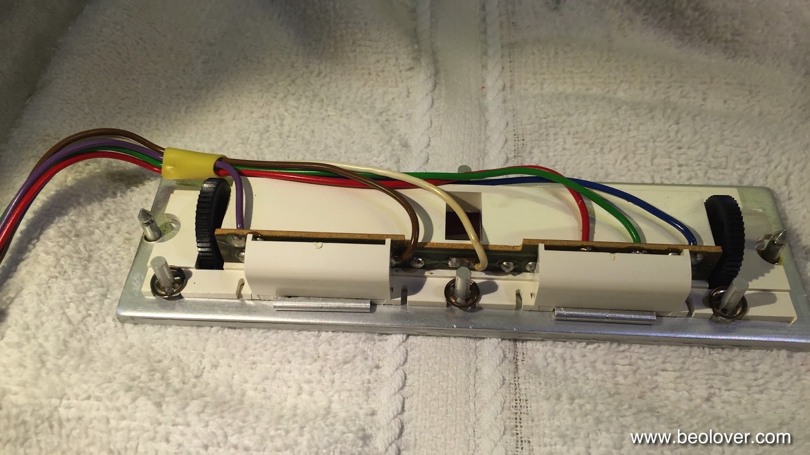
The bulbs can be accessed after removing the two covers:

After unsoldering the leads the bulb assemblies can be slid out:

Now the PCBs can be installed. It is important that they sit flush with the aluminum surface:

And then the covers can be replaced:

And that is it!


Beogram 4002 (5521): Replacing the Tracking Sensor Light Bulb with a SMD LED

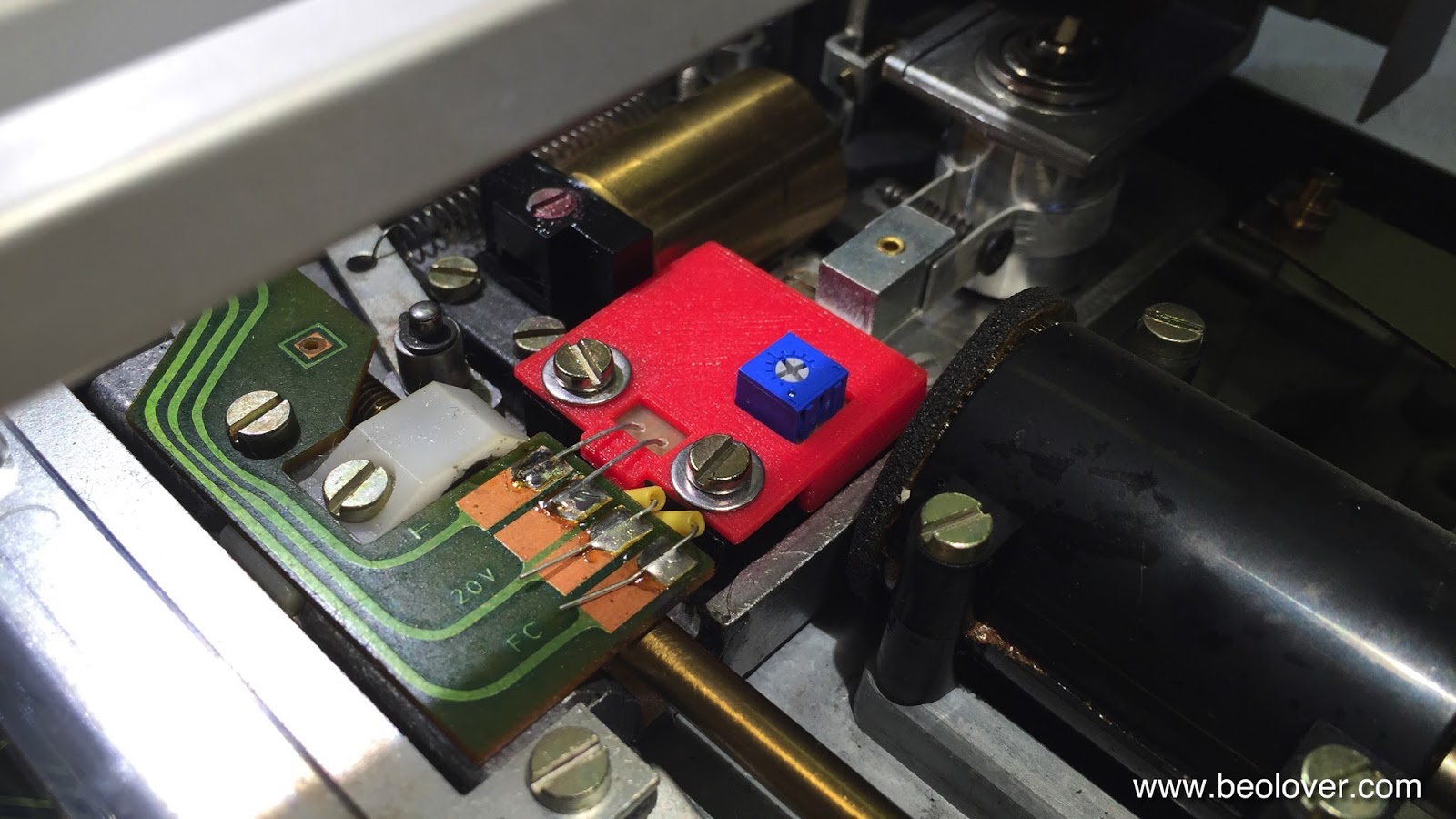
The Beogram 4002 that is on my bench right now came with a broken tracking sensor light bulb. I replaced the bulb housing assembly with my SMD LED based drop-in ready replacement part. This unit was recently redesigned on the occasion of a Beogram 4000 restoration to feature an integrated intensity trimmer, which makes the adjustment of the tracking sensor feedback much more straight forward. The trimmer allows to fine-tune the feedback after the mechanical positioning of the light sensors below the light source. The adjustment process is discussed in detail in this video

This shows the original setup of the tracking sensor:


Here is a picture of the latest iteration of my design in comparison with the original bulb assembly after I removed it from the tracking sensor:

This part is available to other B&O enthusiasts. Just send me an email.

This shows the installed part:

Once the LED assembly was soldered in, I performed the adjustment procedure as shown in my video to achieve that the carriage motor starts advancing after 2±1 rotations of the record after lowering the needle onto the record. This restored the basic functionality of this Beogram. On to replacing the RPM light bulbs with LED assemblies.


Wednesday, December 2, 2015

Beogram 4002 (5521): Rebuilding the DC Motor

I started working on the Beogram 4002 that recently arrived. When doing my initial assessment, I noticed that the DC motor has completely dry sleeve bearings and so every time it would turn on without the belt and platter installed, it would emit a shrill noise due to the high RPM without a load. So this had to be fixed first. There must be peace and quiet in the Beolover's lair (and some nice vinyl playing while I do my work...;-). Here are a few pictures taken during the process. this shows the motor in-situ:

After removing the mounting plate, unscrewing the two screws that hold the motor to it and removing the glued on pulley (this may require some carefully administered force with a large screw driver to pry it off), I opened up the outer enclosure and extracted the motor:

Then I opened the motor up by removing the bottom shell that contains the brushes and the feedback coils:

Nice classic design! Then I extracted the rotor after removing all glue remnants on the shaft (this is important since otherwise the shaft gets stuck in the upper sleeve bearing and then damage can ensue:

Once at this point, all that is needed is to clean the commutator and the brushes with a fiberglass pen, lubricate both bearings with some silicone grease and then put everything back together in reverse. Note that it is crucial to make sure that both brushes are fully inserted onto the commutator before closing the motor back up. The pulley needs to be glued back on, too. Super Glue Gel works nicely. 

I did all that and installed the motor, and now it spins very quietly. Time to enjoy some vinyl! (just ordered an original 70s pressing of Miles Davis' "E.S.P", one of my favorite jazz records of all time)! - let's see if my vinyl record cleaner can salvage it...I really started liking using it...;-)


Sunday, November 29, 2015

Beogram 4002 (5521): A New Arrival - First Impressions

A Beogram 4002 (5521) model in nice cosmetic condition arrived a couple of days ago for some TLC. The unit came with an indication of dead tracking sensor and 33 RPM light bulbs. It also came double boxed, which helped ensure uneventful travels (I recently made a video describing preparation for shipment and packing of a 4002/4. It is posted here). This shows the inner box:

and after taking the unit out: The foam pads held the sub platter down. Very important are the strips of no-residue tape holding the arms and the RPM panel in place during shipment.

The condition of this 4002 is very good except a few minor blemishes like a small shaved off bit of veneer on the right corner of the plinth:
The keypad is also in pretty good condition showing only minor finger marks on the coating:

The hood has the usual scratches commensurate with nearly 40 years of service:

Remarkable is that the Beogram 4002 lettering is missing on the aluminum trim in the back of the hood:

Finally there are a few marks on the arm weight cover, which hopefully can be removed:

Operationally, I noted that in addition to the dead light bulbs the motor urgently needs lubrication. It is emitting shrill noises when running without platter installed, a clear indication of dry sleeve bearings. Furthermore, the transport locks are disintegrating as is evident from the telltale orange plastic fragments distributed throughout the unit:

Unfortunately, the MMC20EN cartridge that came along has a suspension problem. The cantilever is at an off angle. It is interesting to note that the last 4002 that I restored also had an EN cartridge with exactly the same issue. I hope this is not a pattern...Here are a couple pictures:


This can be fixed by Schallplattennadeln.de or Soundsmith. Waiting for a reasonable offering on ebay is another option. In summary, however, I would say this 4002 is a pretty good starting point for a restoration.