Featured Post

Beolover SyncDrive: DC Platter Motor Replacement for Beogram 4002 and 4004 (Type 551x and 552x)

Late Beogram 4002 and the 4004 (Types 551x and 552x), which have DC platter motors instead of the earlier synchronous AC motors usually suff...

Showing posts with label speed. Show all posts

Friday, September 25, 2020

Beogram 4002 (5503): Unit Switches Immediately to 45 RPM After Pressing Start

The Beogram 4002 (5503) that I am currently restoring exhibited a strange phenomenon when I tested it the first time after rebuilding all its functional parts (more about this process in a subsequent post):

After pressing START the carriage began to move while it immediately switched to 45 RPM. Pressing the 33 key switched it back to 33 RPM, but only as long as the key was pressed.

This immediately suggested that either TR3 or TR2 had an issue. Let's have a look at the relevant section of the circuit diagram:


This is how the speed selection works:
The base of TR3 is connected to the collector of TR4, and the base of TR4 is connected to the collector of TR3. Resistors 5R1 and 5R2 act as pull-up resistors together with the light bulbs IL1/2. I guess the resistors were added to keep the deck working even if a bulb burned out.
This causes a flip-flop behavior: When the base of TR3 is shorted to ground via the 45 switch in the keypad or TR2 (that is activated by the carriage as it travels towards the set-down point for singles), TR3 is turned off for a moment, causing its collector to go high, which in turn pulls the base of TR4 up, and that drives the collector of TR4 to GND since TR4 turns on. This then keeps the base of TR3 permanently grounded and the deck is running at 45 RPM (via switching TR6 on which changes the oscillation frequency of the Wien Oscillator to drive the AC motor at a higher RPM).
The opposite happens when the 33 key is pressed. This causes TR4 to be off and TR3 on, and so TR5 is turned on running the oscillator at a lower frequency.

I removed TR3 and checked it with my transistor tester:

Apparently it had turned into a voltage divider!...;-).
I replaced TR3 with a generic BC547B and that fixed the issue.

Monday, August 24, 2020

Beogram 8000: An Exploration of the Platter Speed Sensor (Includes Oscilloscope Traces for the Most Important Signals)

I recently received a Beogram 8000 as a parts unit for repairing another Beogram 8000. I wanted to exchange the circuit boards in the hope to alleviate a strange issue that I sadly was not able to figure out. So I rebuilt the boards of the donor 8000 and then plugged them into the other unit.
And then my fun exploration of the platter speed sensor began...;-). Here is what happened: I plugged the Beogram in, and pressed Play. Immediately the platter ramped up madly to about 100 RPM and the "33.33" never appeared (it shows that a stable speed has been reached by the system). The display stayed at "33". 

Head scratching etc...ensued. The first thing I did was plug the board into the other Beogram to see if its platter would also go out of control. It did not. So what gave?

Well, it turned out that some of the Beogram 8000 with old style boards (i.e. with the two piggybacked small boards on the upper end of the main board) did already come with the speed sensor used in the later Beogram 8002. This are the two circuit snippets in comparison:

First the older version:
Note R46 and R47. They are on the main board in this circuit. Now look at the corresponding Beogram 8002 circuit:
Here, the resistors are on a small board attached to the sensor located under the sub platter. We also see that the value of R46/R2 changed and that R47/R3 carries an "X" now, indicative for the somewhat "semi-exploratory beta release approach" applied for these boards (I do not know of any consumer product that has so many different versions and slight undocumented changes than these B&O circuits). I think the X is a sign that they used different IR LEDs and photosensors during the production run of these turntables. 

Anyway, lets have a look at the two sensors as they are mounted in the Beogram:
Again, first the old style setup: Front
 and back:
And now the newer type with the added circuit board:
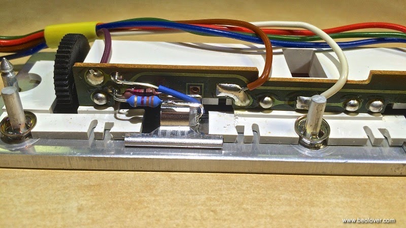
You can see the two resistors on the front of the board. The upper one is for the IR LED and the lower one for the sensor:
This is how it looks from the back:
Due to this difference the main board needed to be modified for the new sensor version. This shows the relevant square inch of the board configured for the old style sensor:
Note that R46 (big resistor that is mounted horizontally) is present and also R47 (red red orange 22k on the left, vertical). Now let's have a look at the board configured for the new sensor style:
R47 is simply missing, and R46 is replaced with a jumper wire!

And there lies the danger when replacing boards without checking what sensor type is installed:
When an old style sensor setup is plugged into a board configured for the new sensor like it happened to me, the LED is directly connected to the +15V rail via the jumper wire, which will probably cause it to be super bright for about 1 microsecond and then dark forever. Well, some people say it is better to shine brightly for a brief moment than to be a dull boring light for a long time, but in this case I get to figure out what modern LED can replace the original LEDs...;-).
I suspect the OP240 may be a good starting point since it can be used to replace IR diodes in other spots in this vintage of B&O. We will see...probably another post coming up sometime in the near future...;-).

Anyway, I ended up transplanting the new style sensor along with the newer boards and that yielded a working setup (again). For the sake of documentation I measured the relevant signals in the speed sensor setup:
This is the signal right at the sensor (P4-pin7):
This signal is cleaned up to a square by the opamp IC1 which is configured as a 5V comparator:
The above trace was measured at pin 14 of the opamp. This signal is subsequently divided down (R51/R50) that the micro controller can digest it, yielding this signal at P6-pin 2:
And that is it about the speed sensor of the Beogram 8000!


Monday, October 31, 2016

Beogram 8000: Repair of Platter Brake Circuit

After replacing the electrolytic capacitors of the Beogram 8000 that I am rebuilding right now and fixing the scraping subplatter issue the unit was again functional and ran smoothly at 33.33 RPM. However, I noticed that after pressing stop and the return of the arms to the home position the platter continued to spin for a long time until it finally came to a rest. The 8000 has a low friction bearing and there is no belt due to the linear platter drive. So there is very little friction overall once power is cut to the motor stator coils. That is why the designers of the Beogram gave it a motor brake that reverses the motor phases to essentially run it in the opposite direction for bringing it to a fast stop. That makes the humming noise when the platter comes to a fast stop.

This shows the relevant portion of the circuit diagram as shown in the Technical Product Information manual:


The motor stator coils are OL1. This are the two big coils that 'hug' the sub platter (which is the rotor of the motor). These coils are phase shifted by the motor cap 4C1. This is basically the same setup like in an AC motor 4002. The motor is driven by the Drive System, which is essentially a push-pull stage that follows the grid frequency taken from a dedicated transformer coil (4T1A) and which regulates the current through the stator coils that is produced by transformer winding 4T1B (the winding shown above the stator coils in the above schematic).
The brake circuit is is essentially formed by TR 31, TR32 and TR33. Once pin 37 goes low, TR31 is turned on (and the drive system turned off via TR27 and TR28). In the process TR32 turns on which then via D39 pulls down the base of TR33. TR33 turns on and the positive half wave of the 60Hz signal from the 4T1B winding is fed into the opposite end of the left coil of OL1 via D40. This reverses the motor phase relative to the normal signal.
The 'reverse drive' aspect of the brake system can be seen by a simple test: Connect the base of TR31 to ground with the unit in standby and the platter starts spinning backward!

It turned out that the brake malfunction in this unit was caused by a broken trace. The trace that connects the collector of TR31 to R110 was cut through, probably the consequence of a previous 'repair' attempt. This broke the chain of command between TR31 and TR32, so when the microcontoller said "brake!" TR32 did nothing, and TR33 remained off, which prevented the reverse phase signal to be applied to the stator coil. Since power to the coils was still cut via TR28, the platter simply spinned until mechanical friction finally stopped it...

Below is a photo of my fix: I soldered a small piece of 'magnet wire' between the relevant solder spots: Magnet wire is good for such tasks since it is coated with a special polyurethane coating (so one can wind a magnet without making short circuits between the windings) that burns off when touched with the soldering tip. Very convenient for making connections with short pieces of wire where it would be difficult to take the insulation of mechanically with a stripper tool.

After this repair the unit 'fired on all 8' again (ah the good old days when most real cars had a V8!)
On to mechanical adjustments and fixing the cosmetic issues of this unit!

Sunday, September 11, 2016

BeoloverRPM: Redesign of Enclosure

No design is ever final! And so I completely revised the enclosure and the base-attachments for my BeoloverRPM device that allows the precise measurement of the RPM of a Beogram. A very useful tool for adjusting the RPM when servicing the deck, or for occasionally checking the RPM as the main belt ages etc...

I sold a number of them since I made the first design available in 2015, but it turned out that the 3D printing of the enclosure had some reproducibility issues due to my use of dovetails to match the different attachable bases with the main unit. Dovetails are difficult to print with 3D printers due to the need for exact tolerances, and today's consumer 3D printers are just not there yet.

So after I ran out of the BeoloverRPM units I manufactured with the original design, I decided to completely redesign the enclosure with the limitations of 3D printing in mind to fill a recent order. Here are a few impressions:

This is what is in the box:

On the right is the BeoloverRPM device with its sensor sticking out to the right. It has a small display that shows the RPM and min/max values as they establish over time. It can also send a stream of data to a computer via the USB port allowing the generation of a RPM vs. time curve. This is very valuable if there are intermittent RPM issues, that are often difficult to discern or reproduce when just listening to records.
The parts on the left are the three different bases, that can be attached to the main unit. They allow clamping to different Beogram chassises (they come in different metal frame strengths) when the deck is in service position, or putting it on top of the enclosure next to the platter. The unit is powered via a USB cable connected to a computer. This cable is also used to extract the data stream from the unit for RPM logging if so desired.

This shows the frame clamp in action:
and this shows it on top of the enclosure using the flat base attachment:
The functionality of the redesigned BeoloverRPM stayed the same, i.e. the demonstration in my video still applies. Check it out here.


Friday, March 11, 2016

BeoloverRPM: RPM Measurements on a Beogram 8002 and Comparison to a DC Motor Beogram 4002 (5513)

My recently developed BeoloverRPM device determines the measured RPM via the time it takes between the 'ribs' on the platter to cross the sensor field of vision. It is simple math to determine the RPM from that, and I was pretty confident that my measured absolute RPM numbers were accurate. However, there is always the possibility of human error, and so I was itching to test the BeoloverRPM on a microprocessor controlled Beogram 8002, which should have a very good RPM accuracy and stability.
So the Beogram 8002 that I just resurrected was in the 'right place at the right time' for this! I used my most recent version of the BeoloverRPM that can be set up on top of the aluminum plates, i.e. the Beogram does not need to be put into service position for a RPM measurement. I did two measurements, for 33.33 RPM
and for 45 RPM:
And it appears the Beogram 8002 and the BeoloverRPM microcontrollers are in happy agreement! The Beogram is spot on, and the BeoloverRPM appears to deliver a precise RPM measurement.

I measured a RPM performance curve for a few minutes while having my 7" test single (Donald Byrd: Black Byrd) on it. This graph shows the curve in comparison with a DC motor Beogram 4002 (5513) in perfect condition:
The red curve on top was measured on the Beogram 8002, while the blue curve below represents the performance of the 4002. We see that both units have a periodicity in their RPM, but the 8002 has a noticeably smaller variation than the 4002. The periodicity itself is unavoidable in a feedback-based control system since a PID mechanism needs some change to be able to operate. The art of designing such systems is to get the change as small as possible, while still being able to run the mechanism in a stable way.
But we clearly see here that a microcontroller based feedback system is superior to an analog system that depends on temperature, component tolerances and probably the moon phase (that was a joke...;-). In practical terms this difference is probably not perceivable by a human ear, but the 8002 definitely represents progress. I am curious to see how the AC motor Beograms perform in comparison...stay tuned for the next episode of this exciting unfolding story...;-)


Monday, February 15, 2016

Beogram 4002 (5513): Replacing the RPM Scales Light Bulbs with LEDs and a Further Improvement of the RPM Stability

After rebuilding the DC motor and the main PCB of the Beogram 4002 (5513) that I am restoring right now, I replaced the incandescent light bulbs that provide the back light for the RPM trimmer scales in the control panel with SMD LEDs. This shows the replacement boards that can directly be soldered into the solder points of the light bulbs:
Here is an impression of the installed boards:
These assemblies are available to other enthusiasts. Just send me an email. This video shows how to install the LED boards.

The interesting aspect here was that the user accessible RPM trimmers in the control panel were the remaining part of the DC motor control system that I did not touch so far, and there were still some minor spikes in the last 24 hrs RPM measurement. So I was curious where these spikes originate and after replacing the bulbs I measured another RPM spectrum. This shows the four spectra that I measured so far in comparison. The top spectrum is the latest one with the LEDs installed:
The bottom spectrum with the large spikes was measured initially before I started working on this unit. The second spectrum was measured after rebuilding the motor. The third spectrum was measured after replacing the RPM relay and the RPM main trimmers on the circuit board. This one was already very good and mostly within the ± 0.05% 'corridor' that is allowed per service manual, but there were still some small spikes every few hours. After the LEDs were installed the spikes were gone, too. 
I am currently hypothesizing that the reason lies in temperature related effects. The original light bulbs get pretty warm and over time the entire RPM panel heats up. This may cause minute movements of the RPM trimmers that are in this panel, resulting in RPM drift that is subsequently compensated by the control system. This results in brief speed variations until the set RPM is established again. With regard to the question why this is not seen in all Beograms that still have the original bulbs installed (like this one, for example), well, I think that the trimmers can be in different states of oxidation and/or contamination, and that some react more sensitively to temperature changes than others.
At any rate, it seems that this Beogram's RPM issues have been cured. On to the remaining restoration tasks!

Saturday, January 16, 2016

BeoloverRPM: Now with Display!

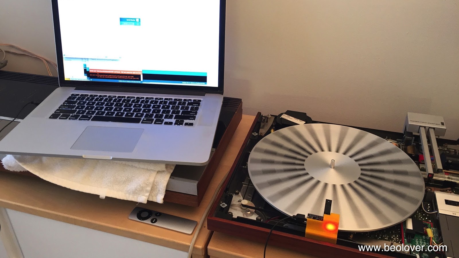
This is an update to my earlier post about my BeoloverRPM device. It allows the measurement of RPM performance of Beogram 400x models over time. It is also very useful for precise RPM calibration. I now tested the original version on a few Beograms and I felt a display would make it much more pleasant to use for simple RPM adjustments in addition to the RPM vs. time serial port printout. Tonight, I finally figured out how to program a small display that I integrated into a modified enclosure of the unit. Here is an impression of the current setup:


Right now it just shows the actual RPM...I will fancify this readout a bit more and then this should be ready for primetime.

Wednesday, December 23, 2015

BeoloverRPM: The Shop Version

This is a follow up to my initial post about my BeoloverRPM device that can be used to quantify RPM stability and fluctuations in Beogram 400x and 8000x models (essentially all models that have 24 radial rubber strips on the platter).

I realized that a main application of the BeoloverRPM device is precision adjustment of the RPM in the analog 400x models. With a currently estimated precision of better than 0.03% the Beolover RPM device substantially outperforms the standard calibration discs that use the grid frequency from a light bulb, and also the 'AC motor Beogram way' of adjusting the motor frequency with an oscilloscope. Both of these 'traditional' methods yield maybe a precision of 1%. Similar errors arise when using a test record and a 3.3kHz or 1kHz tone...oscilloscopes are just not that great when it comes to measuring frequency precisely. A better way is to use a spectrum analyzer with a test record, but even this is fraught with significant errors due to non-centered records and noise issues. 

In difference to these analog methods the BeoloverRPM device precisely measures the time that it takes for the black ribs to pass by the optical sensor, and microcontrollers are very good at measuring time precisely due to their quartz oscillators and their ability to do things very quickly. In fact it mimics the way the 800x models measure the RPM for their feedback control mechanism. And they are very precise at keeping 33.33 RPM over a long period of time. The BeoloverRPM is based on processor interrupts generated by the optical sensor, which essentially means that the error of the measurement comes mainly from the optical performance of the sensor. This remaining error is dealt with by doing a statistical real-time analysis of the measured data. The generated standard deviation output allows monitoring the quality of the measurement and/or the performance of the motor.

Using the BeoloverRPM device for RPM adjustment requires that it can be securely mounted on a Beogram while it is in service position so one can access the base RPM trimmers for the base RPM adjustment. This meant I had to come up with a different design of the system. I realized that it is best to clamp it directly on the metal frame of the enclosure. This allows to be close to the platter while giving a high mechanical stability to ensure a stable sensor position relative to the platter (correct distance is very important for the accuracy of the sensor).

Here are a few impressions of the current state of affairs. This shows the system in action:

Doesn't the power LED look pretty as it shines through he orange plastic print??...;-) The device hooks up to a laptop via a standard mini-USB flex cable. It simply bangs its data through the serial port in ASCII, which allows to use any terminal software on the computer to do the readout. I use the Arduino IDE's serial monitor. The device is now based on an Arduino Nano board with a CH340 USB interface. This makes it necessary to install the appropriate USB driver for this chip. Other than that it is 'plug and play'. The main advantage of this re-design, however, is that there is no more cable between microcontroller and sensor. This makes it much more straight forward with regard to assembly and use stability.

Here are a few detail shots. This shows the final design in front of the preliminary design studies of the plastic cradle (it is notoriously difficult to make a 3D print of a small part to fit something else precisely, and usually only extensive trial and error results in a satisfying fit):

I designed a spring clamp at the bottom for sticking it on the Beogram frame since the 4000 has a thinner frame than the later 4002/4 models. That way the cradle fits on both types:

The small slot is for pushing out the circuit board in case one needs to extract it. It makes a pretty solid press-fit with the cradle. Here is a detail photo how it clamps onto the Beogram frame:

A very solid fit for a precision RPM measurement! I want my customers' vinyls to play at the correct pitch! I am thinking about a 'consumer version' based on my initial design, which could have a direct LCD (or even a 'B&O style red LED 7-segment 4 digit back to the 1984 future style'...;-) display readout, so one could do a RPM check once in a while (yes, there is indeed some drift over time and depending on temperature in these classic analog designs) and compensate with the user accessible RPM trimmers on the control panel for continued precision listening enjoyment. This is Beolove!


Thursday, December 17, 2015

BeoloverRPM: Beogram RPM Calibration Device

Sadly, the Beogram 4002 that I restored a little while ago did not pass muster. It had initially come  to me with an indication of sudden and gradual RPM fluctuations and I thought I had fixed the issue by replacing the RPM relay and the trimmers as well as the DC motor, which showed a strange feedback signal whenever the fluctuations occurred. But not so. While the phenomena were somewhat alleviated, some spontaneous variation still occurs occasionally. Per my customers description it happens maybe once per LP, i.e. it needs to be treated as an intermittent issue. Which are notoriously difficult to fix. 
I decided I needed to be able to measure and quantify the issue before I would be able to attempt another stab at fixing it. The Beolover never gives up, but this one is a tricky one. The last few days I worked on designing the "BeoloverRPM" device, which now allows me to quantify and monitor the RPM of a Beogram with fairly high precision (I think it maybe about 0.03%) over time. I also implemented an automatic fluctuation detection mechanism based on monitoring the standard deviation of the measurement. 

I designed a sensor head, which uses the black ribs found in the Beogram 400x and 800x models to detect the RPM of the platter. Here are a few impressions. The front is curved to fit the platter circumference, and the reflective optosensor unit extends via a fork over the platter

I implanted two M8 bolts into the back of the unit to give it some more weight so it would sit securely next to the platter:

Here is is shown in action measuring the platter of the Beogram 4000 that I just finished up:

It appears to be floating due to rubber feet inserted into the bottom of the body (I was inspired here by the Beogram 8000's rubber bumpers that dampen the impact of its hood when it closes)
The most crucial design parameter was the distance between sensor and measured features. Its optics are fixed, and I determined the best measurement resolution results at a distance of 9 mm. I printed several versions of the housing until I got that distance about right.

Once I had the sensor and verified that I could use it for RPM measurements I sat down and programmed an Atmega328p (aka Arduino) to measure the RPM and do some statistical evaluations. At this point the firmware is able to log the RPM and the standard deviation in timed intervals (10s in the example below). It also detects sudden deviations through monitoring the difference between the running mean of the standard deviation and the current standard deviation. This difference is quite sensitive and a proper threshold allows to hone in on a certain level of fluctuation.

Here is an impression of the printout that is generated:

The ***-marked % deviations were the result of slightly touching the platter with my finger a couple of times. It is interesting to note that the RPM shows as ~33.71 even though I calibrated the RPM of the Beogram 4000 using the AC motor frequency as specified in the Service Manual. It is obvious that this calibration is about 1% off. Naturally I wondered if a measurement error would be responsible for the discrepancy, but a test of the BeoloverRPM device on my Beogram 8000 revealed a proper measurement of 33.32 RPM, which is very close and possibly even at least partly a result of the Beogram 8000 being slightly off (the Service Manual specifies a 0.02% RPM accuracy).
As a next step I will implement an external trigger function for my oscilloscope that I can measure the vitals of a turntable at the moment a fluctuation occurs. Hopefully, this will allow me to figure out what the issue is with the fluctuating 4002! This is Beolove!


Thursday, December 10, 2015

Beogram 4002 (5521): Replacing the Electrolytic Capacitors, New Relays and New RPM Trimmers

It was time to replace the electrolytic capacitors of the Beogram 4002 that is currently on my bench. These units have many tantalum capacitors, and it is a good idea to replace them at this age. They can die a fiery death due to the highly oxidizable nature of the Ta electrodes in them. Here is a picture of the original board. All the blue and red 'dots' are Ta capacitors:


Another standard item of my restorations is to replace the trimmers and the relay in the DC motor RPM control network. Oxidized trimmers can cause drift of the platter speed depending on the temperature of the deck (and the moon phase...;-), while the relay is not encapsulated and hence prone to oxidized contact issues after almost 40 years of service.

I recently developed a replacement relay assembly for the Beogram 4000 and early 4002 models based on a modern encapsulated SMD signal relay. However, this Beogram is a later model, which was already fitted with a more modern relay made by National. This relay is still available as new original stock (NOS) via vendors on AliExpress and similar Asian outlets. However, modern relays are much superior in their design due to modern encapsulation technology and the promise to last for many decades. It is good to keep in mind here that NOS parts are still 30-40 years old and old technology, they just were not used. But oxygen hat its go on them, and so we can expect that the contact tabs are almost as oxidized as in the relay installed in this Beogram 4002!

Hence I modified my design to fit into the later models, too. Here is a picture of the revision of the drop-in replacement relay assembly:
This picture shows the 25 turn 5k trimmers prepared for installation:
This is a picture of the main PCB after replacing everything:

A detail of the relay and RPM trimmers together with the original relay:

This shows the trimmers from the top side of the PCB:
It is important that they are accessible from the top, so one can trim the RPM while the deck is running without having to take out the main PCB.

When replacing the capacitors, of course the main reservoir capacitor of the power supply also needs to be replaced. This shows the original can:

And here the replacement:

I designed a 3D printed adapter enabling me to clamp a modern 4700uF capacitor in the space of the original unit.

After the main PCB I did PCB #8 that sits underneath the keyboard, and which contains the output relay. Here is a shot of the original unit:
I usually install a new relay, replace the time constant capacitor for the relay, and also install a grounding switch that allows to tie system and signal grounds together if necessary to squash humming issues. Here is a picture of everything installed:
After these replacements I put everything back together and then I tested the unit...all went well. This concludes the electronic rebuild. On to the adjustments and alignment of the platter, chassis and the arms!


Monday, September 21, 2015

Beogram 4002: Replacing the RPM Indicator Bulbs with SMD LEDs

I continued working my way through replacing the lightbulbs in the Beogram 4002 (5513) that I am restoring right now. Today was RPM indicator day. I took this as an opportunity to further improve my LED replacement approach. In an earlier post I described how to replace the incandescent bulbs with the red and green LEDs of a RGB through hole 5 mm LED. This worked fairly well, but I was not 100% happy with the homogeneity of the back illumination of the RPM trimmer scales. The issue with standard through hole LEDs is their directed emission pattern out of the top of the LEDs. This made it necessary to sand their bulbs into a matte surface and also painting the tops black to prevent a too high emission on one side of the trimmer scales. 
My latest approach is based on my current approach to implanting LEDs for the position scale illumination of Beogram 4000s. I changed the PCB shape to fit behind the bulb covers of the 4002 bulb housings, and I adapted the current limiting resistors (10k for green and 2.5k for red) to the 21V operating voltage and the different illumination angle of the diffusing cavity. I made a short video about this updated approach:


Monday, September 7, 2015

Beogram 4000: Replacement of a Stuck RPM Relay with a Modern Encapsulated SMD Relay

The Beogram 4000 that I am currently restoring was not able to switch the AC motor to 45 RPM. After replacing the incandescent light bulbs in the control panel it became clear that, while the 45 RPM button would properly illuminate the 45 trimmer pot, the motor would not change its speed. I traced the signal, and it turned out that the relay was broken. The relay simply switches different resistor networks into the feedback of the Wien oscillator thereby changing its resonance frequency.

The issue with replacing vintage relays is that modern units usually are much smaller and also have a more standardized footprint. This vintage relay actually has an unusual pinout in that the two throws are not mirrored across the relay like in modern units, but are different. The translation between modern and vintage relays was made with a breakout board that matches the pinout of the original relay.

I made a short video about this process. It explains the circuit and gives a demo of the new relay click. This is important in my opinion, due to need to get an audible feedback when pressing one of the RPM buttons. All other buttons give a direct mechanical feedback, i.e. this seemed important. Here is the video:


Here are a couple high res shots of the breakout board. Front:

And back:
This design drops directly into the solder points of the original relay.

Wednesday, March 18, 2015

Beogram 400x: Replacing the Tracking Sensor Light Bulb with a Drop-In Ready LED Assembly

I used my current Beogram 4002 (5513) restoration project as a chance to redesign my earlier approach to replacing the incandescent light bulb in the linear tracking sensor with an LED. In my earlier approach (see here), I reused the bulb housing and just replaced the light bulb part with a 3D printed LED assembly that I had designed as an early (and later abandoned) iteration of my Beomaster 6000 4-Channel incandescent bulb replacement method. While this worked well for the Beogram, it had two significant issues: (1) it was not a drop-in ready solution and required a lot of detail-Dremeling of the original housing to get the glued-in bulb housing separated and replaced, and (2 - probably more important) that the LED position was not very well defined and also not impact/vibration stable. No(2) is clearly an issue when shipping the Beogram, i.e. not suitable for a professional restoration.
So I set out to design a part that is drop-in, 100% mechanically stable, and that is precise enough to only require a small adjustment of the tracking mechanism, which can be done by just turning the executer screw (larger adjustments require a cumbersome realignment of the sensor aperture). The adjustment process is shown in the video below.

Here is a picture of the original bulb housing:


It is interesting to note that the bulb is slightly misaligned, i.e. oriented to one side. I suspect that this reflects 1970's production tolerances, and that most tracking sensor bulb housings will have bulbs at various locations. The obvious consequence is that the installation of a bulb replacement will require the adjustment of the tracking mechanism after installation of the replacement part, independent of the part being an original-style incandescent bulb or a LED replacement.

I designed a part resembling the lower part of the original bulb housing, which is responsible for keeping stray light out of the tracking sensor. Then I combined this part with a custom designed printed circuit board that is responsible for operating the LED. 
Here is a picture of the two parts before assembly. The LED is a standard white 0603 SMD LED run with a 2.5 kOhm resistance that it can take the 21V rail of the Beogram. The LED, resistor and the solder points of the leads fit into appropriate cutouts of the housing part:


Here is a picture of the running LED after epoxying the circuit board to the housing. The LED is precisely situated in the middle, i.e. very close to the bulb filament position of the original part:


I updated my earlier video about the tracking sensor light bulb replacement with the new part. It goes through all the steps of replacing the original bulb housing and discusses the tracking sensor mechanism. It also shows how a misaligned sensor behaves, and how to adjust it properly:

Sunday, March 15, 2015

Beogram 4002 (5513): Replacing the Speed Indictor Light Bulbs with RGB LEDs

While I am waiting for a 3D print of the redesigned LED light assembly for the tracking sensor of the current Beogram 4002 (5513) I rebuilt the speed indicator scale lights with RGB LEDs. I essentially followed the approach demonstrated in my recent video:


Here are a couple pictures of the actually rebuilt unit:

Original set-up with incandescent bulbs (covers taken off):


And after replacement. There are two resistors since I am using the red and green LEDs of a RGB LED to get a naturally appearing light reflection on the red scale markers. Amber LEDs make an incandescent-like glow, but they do not contain red light, i.e. red scale markers show up gray and even invisible in absence of natural room light - this is discussed in more detail in the above video):


As usual, I further refined my approach a bit: One of the issues with LED replacements of incandescent scale lights is their considerably more narrow radiance pattern. Light bulbs emit fairly uniformly in all directions, while LEDs usually have a narrow emission angle. This is usually combatted by sanding the LED bulb, but some of the directional pattern remains, even after this procedure. In the above video I used tape to shield one end of the scales from too much light, which allowed me to achieve a mostly identical scale appearance as with the original light bulbs. And this worked fine for my personal Beogram 4002, but for a professional 'commercial' restoration I felt this is not a permanent solution, since tape ages and the adhesive can loose its force etc...Since my main interest is to make these beautiful turntables 'future proof' (Imagine Charlton Heston digging it out next to the Statue of Liberty on the beach, cleaning it and plugging it in and the scale lights work...;-),


I needed a more permanent solution. So this time I decided to carefully apply some black acrylic paint to the end of the bulbs and some to the exposed side. Here is a picture of my efforts:


After a few trials slowly adding more painted areas I ended up with this degree of coverage. It is important to also cover a bit of the side wall of the bulb cylinder to absorb some of the photons in that direction to get an even scale illumination.