Featured Post

Beogram Commander Remote Control: Maybe This is the Final Version!..;-)

This is a follow up to my recent post about the redesigned Beogram Commander remote control board, which now works in both (DC-motor) Beogr...

Tuesday, July 24, 2018

Beomaster 4400 (2419): Amplifier 50W Output Check

As a burn-in test I left the Beomaster playing the FM tuner for 24 hours. I varied the volume level every now and then but always kept it at normal listening levels (soft to loud). The output transistor heat sinks remained cool to the touch all during the burn-in testing and of course the sound was good.

Now it is time to see how the Beomaster does when full output power is requested.

First the test setup. My source input voltage is a 1KHz sine wave at 2Vp-p into the Beomaster 4400 Tape 2 DIN plug.


The output of the Beomaster will be measured using the speaker 2 output connected to my 8Ω dummy speaker loads. These are power resistors with heat sinks mounting on an even larger heat sink as the resistor loads will get pretty hot when full power is applied.


Here is the Beomaster with speaker 2 selected, Tape 2 selected and the volume level set to output 50W (the rated power output into 8Ω as listed in the Beomaster 4400 manual).  I used my DMM to monitor the speaker load to check when 50W was reached. The QA400 analyzer connects to the dummy load as well via a differential probe.


The power test worked nicely. I ran the volume up until I got to 20 V on the DMM. A little bit higher and the Beomaster overload lamp came on as I would expect. I backed the volume down a bit to measure the distortion of the 1KHz signal across the dummy loads.


Both channels measured quite good. Just below 0.02% THD for a 1KHz signal at maximum power.


As with previous amplifier measurements using this setup... I can't really do a direct comparison with the B&O published specifications as their test equipment and methods are different from mine. The best I can do is repeat my own test setup with the amplifiers I restore and collect that data for my reference. In comparison to my recent Beomaster 8000 output tests the THD on this Beomaster 4400 also measures very good. Well below what human ears can hear.

Sunday, July 22, 2018

Beomaster 4400 (2419): No Load Current Adjustment

Here is a quick updated on the Beomaster 4400. Yesterday the Beomaster was powered up for the first time after the restoration. All of the power supply voltages checked out good. Continuing on today I set the no load current. That procedure calls for measuring across the two emitter resistors on each channel with the volume at zero and no speakers connected. The idle current trimmers are adjusted so that each channel is at 10mV to 15mV across their respective output emitters.

To start with I am setting these on the low end of the range so I set each to 10.2mV. I will test with that for a while and monitor the temperatures of the output transistors. Once I am comfortable with that I will look at increasing the output.

Here are the left and right channel adjustments.


I'm afraid I couldn't wait to hear what this amplifier sounds like so I connected up an iPod Nano to TP2 and the Beomaster speaker 1 outputs to my Beovox S-55 speakers (that I always test with in the shop).

I realize it is too early and there are still performance tests to run but the Beomaster sounds great in this first test.

I checked out the FM tuner controls. The large tuning dial and the six presets all work. Stereo decoding appears to be working fine. The signal strength looks strong but I will check everything out further in the next few days.


So far I have had power on the Beomaster for over an hour with it playing through the Beovox S-55 speakers. The heatsink fins remain cool. I will let the Beomaster continue to play for twenty-four hours.


Beomaster 4400 (2419): Reassembly and Power Checks

Today I reassembled the electrical components of the Beomaster 4400 and performed the all important first power on test. The goal here was to verify all of the board component work is correct and the Beomaster can be plugged in, turned on and all of the power supply voltages are good.

I installed the FM boards (PC1, PC2 and PC3) first.


I had removed the shield cover to the main power switch so I reinstalled those parts now.


The last board to install is the PC4 preamplifier board.


As I was tightening the mounting screws of the preamplifier board to the cabinet I was reminded of a problem (in my opinion) with the design of the connector panel. The RCA jacks are too close together. This is also the case on the Beomaster 4000 receiver. I don't own any audio cables with RCA plugs that can mate with the Beomaster 4000 and 4400 receivers. The only solution will be to make my own and use heat shrink tubing instead of the outer shell that comes with the RCA plugs.


You can see that only the bare RCA plugs can fit the space allotted by the Beomaster connector panel.

I always connect Bang & Olufsen source components to the Beomasters so it isn't a problem for me but it is something to be aware of if you are planning on using your Beomaster 4400 for some non-B&O audio source components. The solution in that case is to get an adapter cable that goes from the RCA plugs to a 5-pin DIN plug.

Anyway, just a pet peeve on my part. Continuing on it is time to see what happens when power is applied to this newly recapped Beomaster 4400.  In the case of the older Beomaster amplifiers I like to use a variac with a dim-bulb tester on the first power up. It is just added protection in case I missed something. 


The Beomaster 4400 powered up fine. That is great so now I checked all of the DC voltages in the Beomaster.

Here is the +15 VDC power check where the regulator 0IC1 attaches to the PC5 board.


Next is the +35 VDC rail voltage at TP3 of PC5.


Then the -35 VDC rail voltage at 5R16 of the PC5 board.


I checked the +24 VDC voltages at the emitters of 5TR3 and 5TR4.  Here is a picture of the 5TR3 emitter. Both measured +24 VDC as they should.


Last I checked the -12 VDC at TP15 of PC5.


Very nice. Everything looks good so far. Tomorrow I will start adjusting the no-load current (idle current) and the source levels. Once that is done I will be able to see how this amplifier performs with audio signals.

Thursday, July 19, 2018

Beomaster 4400 (2419): Reservoir Capacitor Replacement and Transistors Remounted

Last night I installed the two new 0C8 & 0C9 10KuF reservoir capacitors. These are the capacitors for the Beomaster ±35V rail voltages.

The replacement capacitors are a little smaller in diameter and length but I found some 105°C Nichicon capacitors that still fit into the Beomaster 4400 mounting bracket.

I reattached the ±35V rail voltage wires using some small terminals.


I added some heat shrink tubing for some added protection.


Here is the completed reinstallation of the reservoir capacitors.


Now I was able to resecure the main (PC5) board in the cabinet. I am using SilPads for the insulators and thermal exchange between the power transistors and the heat sinks.


This Beomaster is now ready for the reinstallation of the small boards.


Sunday, July 15, 2018

Beomaster 4400 (2419): PC5 Recap

Today I tackled the large PC5 board. The service manual titles it the AF Amplifier, Power Supply, Muting and Silent Tuning board. I'll often refer to it as the PC5 board, main board or output amplifier board.

The PC5 board has the most electrolytic capacitors to replace and it has six trimmer resistors.

Here is a picture of the board before recapping.

Beomaster top opened up


Boards and reservoir capacitors removed


Since this board is the largest and kind of difficult to remove for recapping I will take the opportunity to measure the output transistors (the ones mounted to the heatsink). I will also check and reflow solder joints on the board to board wires and the output amplifier transistors.

The transistors measured good but there were a couple of bad solder joints where the transistors attach to the PC5 board.

The recapping of this board takes a while as it has quite a few capacitors. There are a lot of 1uF, 2.2uF and 4.7uF capacitors. I think this particular Beomaster may have set a new personal record for the number of out of tolerance capacitors found. I found 1uF capacitors measuring as high as 4uF.

Here is the recapped PC5 board.


Tomorrow I will install the new reservoir capacitors and this Beomaster will be about ready to try out.

Saturday, July 14, 2018

Beomaster 4400 (2419): Recap Review Leads to Preamp Rework

A nice side benefit of documenting these Bang & Olufsen restorations is that it forces me to review and double-check my work. Several times I have thought a task was complete only to look at the photos of the work and spot a problem.

In the case of this Beomaster 4400 I started thinking about the next few steps of the restoration and when looking at the preamplifier (PC4) board I realized that I had made the source input level adjustments more difficult in the way I installed the trimmers.

The original trimmers are designed for top and bottom adjustment. That is nice but I wanted to replace those single turn, open type trimmers with some Bourns multi-turn, sealed trimmers. The new trimmers only adjust from the top.

Here is a photo of the Beomaster 4400 preamplifier as I received it.


Most of the time these Beomaster receivers still have the seals over the input level trimmers as people leave them per the factory settings. If they need adjustment the paper seal can be broken and the trimmer adjusted from underneath the Beomaster.

In my initial PC4 - preamplifier board recap I oriented the multi-turn trimmers as you normally would on the component side of a board.


Unfortunately that would mean making the adjustments before fully installing the Beomaster 4400 preamplifier board.

Like we do on the Beogram 400x RPM trimmers, I flipped the input level, 50KΩ trimmer resistors over so they adjust from the trace side of the PC4 board.


That is much more practical. The owner can then tweak the input levels without opening up the receiver.

Thursday, July 12, 2018

Beomaster 4400 (2419): Into the Recap

These seventies era Beomaster receivers have a low profile and are quite a challenge to open up into a service position. I like the way the eighties era Beomaster units were designed with some consideration for the service technicians. Oh well, it is what it is. The Beomaster 4400 is an improvement over the Beomaster 4000. There are some board connectors.

Here is the Beomaster opened up and ready for recapping.


The PC5 board has the most recapping work and does not unplug completely for removal. I disconnected enough wires to it so I can get to where I need to with regards to replacing capacitors but I will tackle the PC5 board after I recap the smaller boards.

I started with the PC3 - Stereo Decoder and Indicator Circuit board. It is a good one to warm up on.


Here is the recapped board. For now I am leaving the trimmer resistors as they are on the FM boards. I will replace them as necessary during the Beomaster performance testing. 


Next are the PC1 and PC2 FM boards. There are just three capacitors to replace between them.


...and here are those boards after the recap.


Now for the PC4 - Preamplifier board.


On this board I also changed out the six 50KΩ trimmer resistors as I recapped the board.


Tomorrow I will tackle the large, PC5 board and the two reservoir capacitors.

Friday, July 6, 2018

Beomaster 4400 (2419): New Beomaster Project From Canada

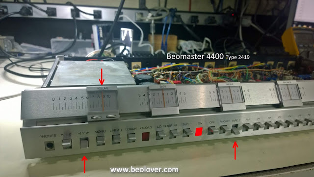
With the Beogram 4002 (5513) project moving into its listening test phase I can put a new project on the workbench. I have been looking forward to this next one as it is a very nice late 70's era Beomaster 4400. This unit comes from a friend up in Canada so it has travelled quite a ways to get here.

When it first arrived I had to see how it looked in a recent Bang & Olufsen MC40 cabinet I acquired.


Looks like a great fit :-)

Now on to the workbench...


Very nice. This Beomaster has been well taken care of.

The task on this receiver will be to replace the old electrolytic capacitors and some of the trimmer resisters. Then I will see what the state of it is.