Featured Post

Beolover SyncDrive: DC Platter Motor Replacement for Beogram 4002 and 4004 (Type 551x and 552x)

Late Beogram 4002 and the 4004 (Types 551x and 552x), which have DC platter motors instead of the earlier synchronous AC motors usually suff...

Showing posts with label as received. Show all posts

Monday, May 3, 2021

Beogram 8002 From North Carolina: Project Start

With the Canada Beogram 4004 in the middle of listening tests (enjoyable testing I should say) I can start looking at the next Beogram project.  

A while back I received a nicely packed Beogram 8002 from North Carolina. 


It is worth noting that the small styro-foam block outlined in green plays an important protective function in the packing of a Beogram 800x turntable.

It secures the top and bottom of the Beogram 800x case where the lid over the tonearm compartment and the Beogram transformer live.

This block prevents the tonearm compartment lid from opening and the transformer assembly from bouncing loose should the Beogram shipping box experience a sever jolt (i.e. drop).


Here is the unpacked Beogram.  It shows the three floating chassis lock down screws still securing the chassis.


Before opening the Beogram into the service position I notice that the dust cover assembly and hinge are not fitting quite right.


Here is the Beogram opened up to its service position.


From the initial service position I opened access to the main circuit board assembly and removed the Beogram 8002 turntable components from the cabinet.


Here is the empty Beogram 8002 cabinet.


Here are the main turntable components removed for working on.


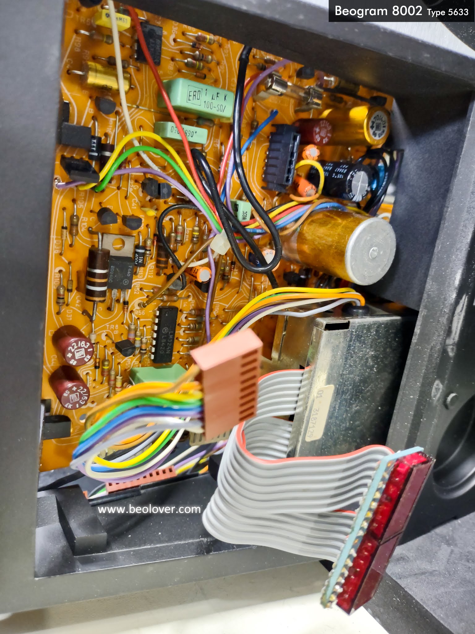
Here is a closer look at the main circuit board and the small microcomputer board.


The electrolytic capacitors all look original in this Beogram.  They are overdue for replacement.

On the output, muting relay board (where the phono DIN plug connects to the Beogram 8002) I can see that there is a broken wire.


I further disassembled the Beogram 8002 dust cover assembly.


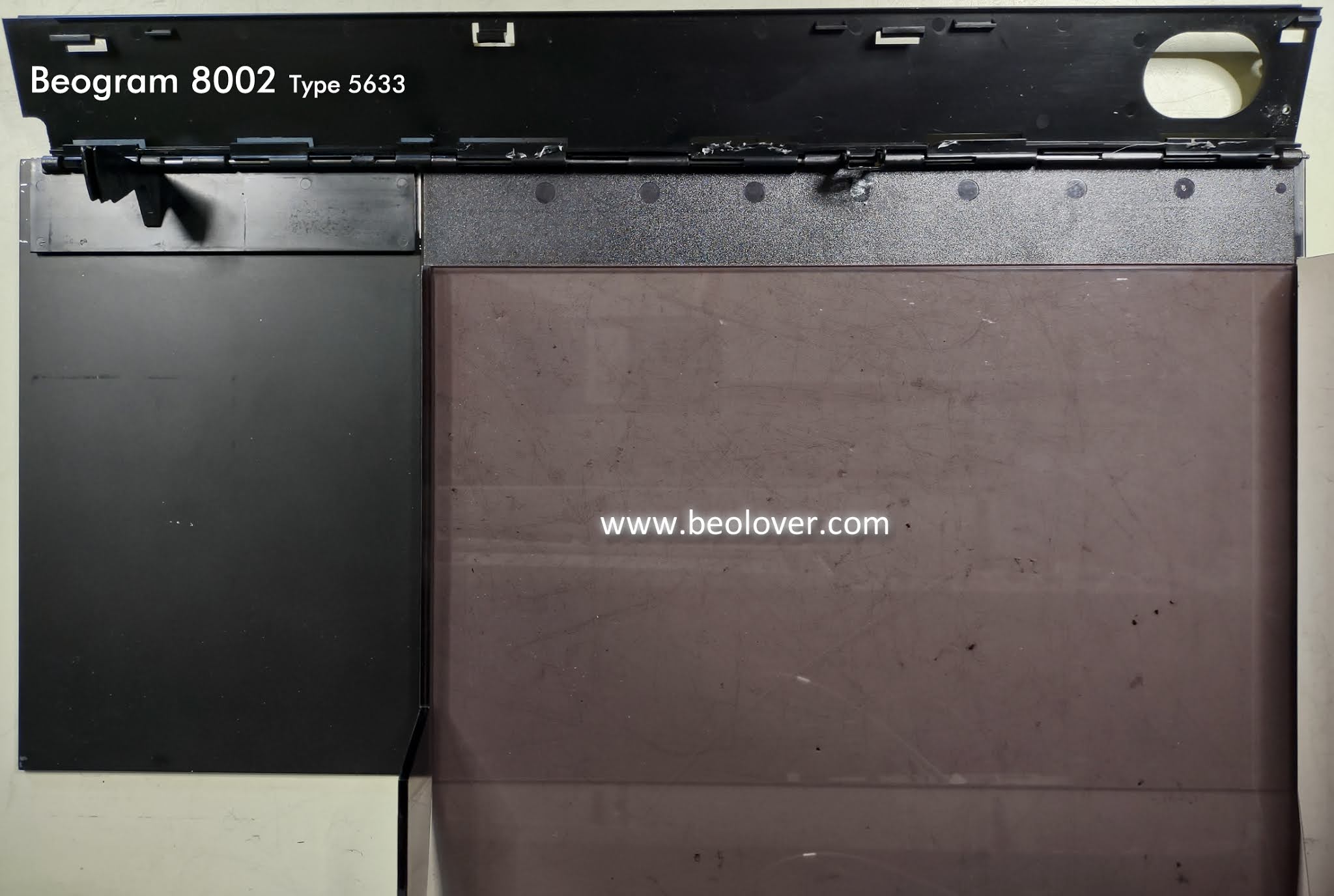
The dust cover assembly is in nice shape overall. 
The small metal hinge assembly for raising and lowering the dust cover is not properly attached to the dust cover. That is preventing proper operation of the dust cover lid.

The damped hinge assembly for the lid over the tonearm compartment is void of any damping grease. That causing operation problems for that lid assembly.
I will have to dive deeper into the Beogram to repair those two items.

Here are some photos of the Beogram 8002 dust cover raise and lower components.


The following photo shows a slick sheet of plastic material (highlighted in blue) that is there to aid the dust cover leaf spring assembly to move up and down.
The photo also shows screw (hightlighted in yellow) that someone added to try and secure the Beogram 8002 dust cover to the cabinet.


Here is a closer look at the leaf spring for the Beogram 8002 dust cover.


Finally...here is the identification sticker on this Beogarm.


Friday, October 23, 2020

Beomaster 2400 Type 2902 - Canada Project First Opened Up

I plugged this new Beomaster 2400 unit in and checked out the lights on it to see if any were burned out.  It turns out that all of the lamps are functioning.


As promised I opened up this new Beomaster 2400 receiver to check the components inside.


The Bass, Treble and Balance slider controls look to be in good shape.


The slider controls on this Beomaster 2400 are a different style than I usually see.  I have seen these before but they have a round bar for the slide control to travel on instead of the usual flat bar.


The black plastic bridge that holds the slider control contacts is different due to the round bar that it attaches to. As a result of that difference these controls don't have the problem of the broken contact mounts that typically require a repair.

Now to take a look at the Beomaster 2400 indicator lamps. 
First, the volume control lamps. I can see that one of these lamps has been replaced in the past.
So this Beomaster 2400 has been worked on before.


Here are the lamps for the Bass, Treble and Balance indicators.
The indicator masks for these controls were is good shape but you can see on the underside of the red lens caps that there is a lot of fading due to heat from the incandescent lamps.  I usually replace the original lamps here with cooler operating LED lamps.  These three lamps are always on when the Beomaster is not in standby and are not vital to any circuitry in the Beomaster.  They simply are powered on and off when the Beomaster comes out of standby and goes into standby.


The last group of lamps are for the FM tuning indicator, FM stereo indicator and the selected audio source indicators (Phono, Tape, FM1, FM2, FM3, FM4 and FM5). There is also a red LED lamp for the standby mode indication.


These lamps do wire into Beomaster 2400 circuitry and factor into the operation of the circuits they are part of.


Now the restoration can be planned and implemented.
I start on that tomorrow.


Thursday, October 22, 2020

Beomaster 2400 Type 2902 - New Project From Canada

 It is time for another Bang & Olufsen Beomaster 2400 restoration. 

This unit comes from Canada and is in really nice condition. 


There are a couple of things to fix on the cabinet.
As with most of these Beomaster 1900/2400 units the original plastic feet are missing.
I will install a new set that I source from Beoparts.

I also noticed that the Speaker 2 on/off plastic lever is missing.  I should have a spare part for that somewhere in my collection of BM1900/2400 parts.


Tomorrow I will open the Beomaster 2400 cabinet and scope out the work to do inside.

Saturday, December 21, 2019

Beomaster 2400: Finished the capacitor replacement

The last two boards to replace capacitors on are the Volume Control and Tone Control/Tuning boards.
Before starting those however I finished up work on the main board by replacing the left and right channel trimmer resistors for the no-load current adjustment (which will be performed later).

Here are the left and right trimmer resistors for no-load current adjustment on the Beomaster 2400 output amplifier.


I like using multi-turn trimmers for the no-load current (or idle current) adjustment. They make fine adjustments much easier.  Here are the new, Bourns 250Ω trimmers next to the original trimmers.


Here are the new trimmers installed on the main board.


The small adjustment screw is also easier to get to for the adjustment procedure once the Beomaster is put back together.

Moving on...here is the Beomaster 2400 Volume Control board recap before and after pictures. There were six tantalum capacitors on that board that I replaced with WIMA MKS capacitors.


Last is the Tone Control and FM Tuning board.


As I saw on the main board, all of the electrolytic capacitors were either way out of tolerance or close to the tolerance limit. Here are some samples of the measurements I made of the old capacitors from this Beomaster.


The next tasks of this Beomaster restoration will be to check and repair the Bass, Treble and Balance slider controls.

Wednesday, December 18, 2019

Beomaster 2400: Recapping the Main Board

Whew! The main board of this Beomaster 2400 is fully recapped now. Seventy capacitors were replaced and there are still a couple of boards left that also need recapping.

Here are a couple of photos of the main board after the recap


The bulk of the restoration work was on this main board recap.

Now let's go back to the start of the recap and look at some of the details.
Here is the board before any of the capacitors were replaced. There are three metal shield boxes on the main board. Each shield box houses one capacitor that I needed to replace. The three metal boxes are highlighted in the picture below. The box in the top right is for the FM Front End, Tuner. The box below it is for the FM Detector. The third box just to the right of the Beomaster 2400 reservoir capacitors is for the remote control receiver.


For me the best way to do the recapping is to just systematically go through and replace each capacitor one by one. I tried removing a bunch at one time then spent a bunch of time rechecking the work to make sure polarities and capacitance values were correct. Doing them one at a time and keeping track of the polarity as each capacitor is replaced is a much safer way to go.

Looking inside each of the metal boxes we find the following.


I found that almost every capacitor, except for the reservoir capacitors and tantalum capacitors, was way out of tolerance. A lot of the capacitors were almost double the capacitance they were supposed to be.

The 10uF, 63V electrolytic capacitor inside the detector box measured over 20uF...and so did all of the other 10uF, 63V capacitors on the board.


The 10uF, 10V tantalum inside the Front End, Tuner box measured okay but I still replace it as I already planned to do in this full capacitor restoration.


The remote control receiver box also had a 10uF, 63V capacitor that measured over 20uF.


The Beomaster 2400 has a small "mod" board installed by Bang & Olufsen at some point in going from the Beomaster 2400 Type 2901 to the Beomaster 2400 Type 2902. The board changed components used for the tape record audio signal and has four capacitors that this recapping exercise replaced. The small board had to be de-soldered from the main board so the trace side could be accessed for the capacitor replacement.


There are three power supply reservoir capacitors that I replaced.
One reservoir is a 2200uF, 25V electrolytic capacitor that is used in the +15VDC supply.


The other two are 5000uF, 35V electrolytic capacitors for the ±31VDC rails used by the output amplifier section.


I replaced the originals with 5600uF, 50V capacitors. They each measured around 5200uF which is nicely in the 20% tolerance of the original value.


As I mentioned earlier, most of the capacitors on the main board were badly out of tolerance.
Here are some examples of what the old, original capacitors measured as I removed them.


The main board is where most of the restoration work takes place on these Beomaster 2400 (and 1900) receivers. I still need to replace the two trimmer resistors on this main board for the Left and Right channel no-load current adjustment. I will finish recapping the last two boards then do the trimmers.