Featured Post

Beogram Commander Remote Control: Maybe This is the Final Version!..;-)

This is a follow up to my recent post about the redesigned Beogram Commander remote control board, which now works in both (DC-motor) Beogr...

Wednesday, December 30, 2020

Beogram 4002 Type 5521: Restoration of DC Platter Motor, Main PCB, and RPM Panel

I recently received a DC platter motor, the main PCB, and the RPM panel from a Beogram 4002 (5521) for restoration. The parts reached me via a personal courier from the Netherlands. As usual I started working on the motor first since it can take a few days until the motor bearings are infused with fresh oil. This shows the motor as received:

I took it apart to get at the bearings:
The bearings are the two small donuts on the black pad upfront. I submerged the bearings in motor oil and pulled a vacuum. Immediately, bubbles emerged from the bearing. This indicates that the vacuum draws the air from the pores of the bearing, making room for oil to inter diffuse:
After about 48 hours the bubbling stopped and I extracted the bearings:
I reassembled the motor and put it aside.
The next step was to rebuild the main PCB. This shows the board as received:
This shows the original 'RPM section' of the circuit in detail,
and the original amplifier circuit of the record detection circuit.
I replaced all electrolytic capacitors and installed a new RPM relay, RPM trimmers and a new high gain transistor for the record detection circuit.
This shows the rebuilt RPM circuit with modern encapsulated trimmers and relay:
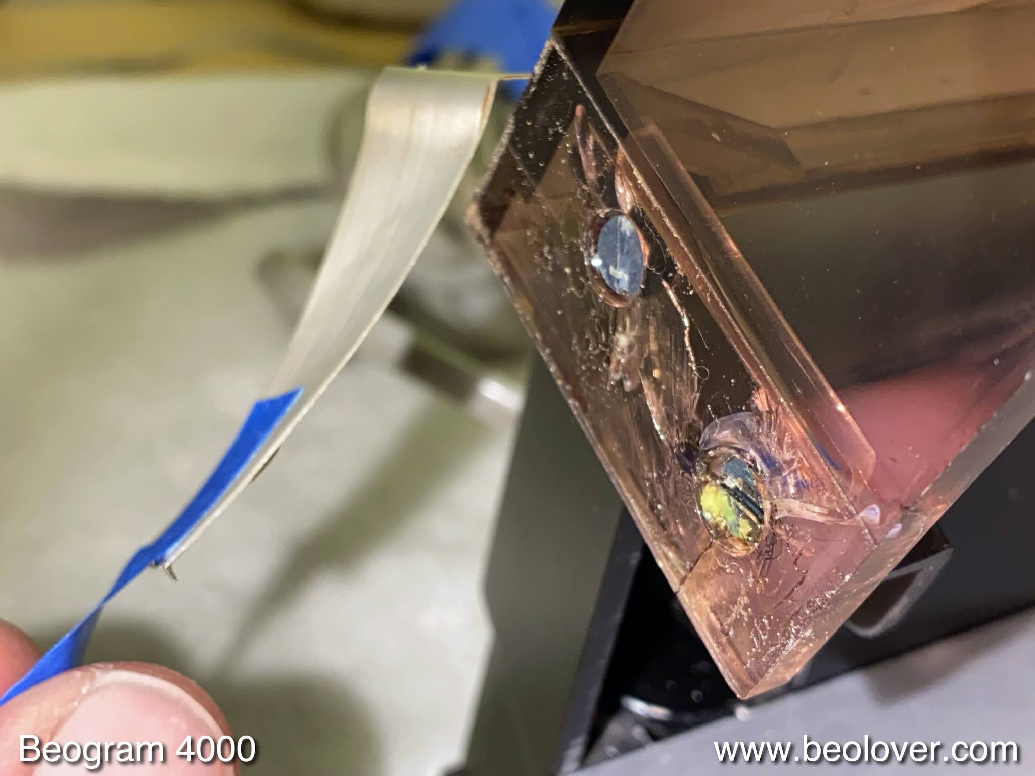
The next step was to replace the incandescent light bulbs in the RPM panel with LED boards. They are the two green squares:
Before I tested everything, I adjusted the new gain trimmer for the record detection amplifier to yield the specified 4V at its collector:
This is an important adjustment to ensure that the absence of a record on the platter is properly detected to prevent damage to the stylus in the event that start impressed without a record on the platter. After the adjustment I installed the trimmer 'below deck' next to the new transistor:

And now it was time to do some tests. First I measured the sensor response above an empty platter and I got a nice ~5Vpp signal as specified in the manual (each dip corresponds to a black 'rib' passing by under the sensor arm - this is how the Beogram detects that there is no record):

So far so good. The final step was to adjust the RPM and measure the RPM stability with the BeoloverRPM device:
It allows logging the RPM in 10s intervals. This is the curve I measured over about 24 hrs:

This is about as good as it gets with the Beogram 4002 DC Platter motors. It appears these components are ready for duty again. Soon they will be sent back to the Netherlands!


Sunday, December 6, 2020

Beogram 4004 DC Platter Motor Restoration

I recently received a DC platter motor from a Beogram 4004 in California for restoration. This shows the motor as received:

I took the motor apart to extract the bearings:
They are the two small donuts on the back pad upfront. I immersed them in motor oil and pulled a vacuum. Immediately, strong bubbling started:
The bubbling indicates that air is being drawn from the porous bearing material by the vacuum. This makes room for the interdiffusion of oil into the bearing. After about 4 days the bubbling stopped and I extracted the bearing from the oil:
Then I assembled the motor and installed it in one of my Beogram 4002s for testing with the BeoloverRPM device, which allows logging the RPM in 10s intervals for extended periods of time:
After abut 24 hrs I had this curve:
This is as good as it gets with Beogram 4004 platter motors. This motor is ready for duty again!


Friday, December 4, 2020

Beogram 4000: A New Arrival from New York

I recently received another Beogram 4000 for restoration. This one came from New York. It came in a Beolover double boxed shipping container and so shipping was no problem. I extracted the unit from its cocoon and put it on the bench:

The aluminum surfaces are in pretty good shape. There are a few small scratches on the platter but nothing too bad:
The plinth is also in excellent condition with very nice corners:
Unfortunately the hood is one of those that have a flimsy plastic imitation Beogram 4000 trim in the back. Also its hinge areas are cracked due to the high strain inflicted by the weight of the hood against the springs that hold it open:
Since all the parts of that cracked area are still present I may be able to patch it back together and put a new aluminum replica trim strip on this hood. If that works, all it needs is a good polishing to be back in service again. I took out the aluminum panels and found an original looking setup, an excellent starting point for any functional restoration:
Luckily, the hard to replace red position indicator is also in good shape:
Unfortunately, the mounting tab for the MMC cartridges has broken off. This is a frequent issue with the 4000 since they used a more stiff and therefore brittle plastic for this first iteration of the 400x series:
Even if the tab is still in good condition I usually recommend replacing it, since even moderate torque when sticking on or removing a cartridge can break it off, and sometimes the broken off part ends up lodged inside the cartridge, and then it can get really expensive.
Luckily, this issue can be fixed with a 3D printed Beolover replacement that is made from a modern material that does not break very easily.

A minor issue are the cracked plinth guidance washers:
They can easily be replaced with Beolover replica washers. 
What I also found during this first inspection was a cutoff mains plug. Not sure why quite a few Beograms come with their plugs cutoff, but here we go:
I did not dare plugging it in just now since my customer had informed me that there was some 'hot electronics smell' coming from the unit when he tried it out. So I will need to be a bit careful. I am sure the root cause will give rise to another interesting episode of my 'A fun evening with...' post series....;-).

In summary, I think this Beogram 4000 is a pretty good starting point for a full restoration to a like-new condition. More about this in some upcoming posts...


Tuesday, December 1, 2020

Beogram 4000: A Very Corroded New Arrival from Sweden

I recently received a Beogram 4000 from Sweden. It arrived double-boxed and there was no shipping damage. A good sign! I extracted it from the boxes and put it on the bench. This post summarizes my first impressions.

First the good: This Beogram 4000 came with pretty decent aluminum surfaces. The platter is in good condition. The lettering on the arms cover was protected and therefore survived. The big and small panels are also pretty good. But we will see after cleaning them how good they are. The unit is pretty dirty.

I took the panels out. Under the hood it seems original as far as I can tell. The main capacitors show signs of leakage, which is almost to be expected at this point in time. The red position indicator is also o.k.. So far so good:
The plinth corners are pristine:
And now the bad:
I have never seen such an amount of corrosion on the black enclosure parts. It is normal that there are a few small spots where the black coating comes off, but this Beogram breaks all records:
Even on the bottom of the enclosure is a lot of corrosion:
The leaf springs that float the chassis are also rusty:
It seems that this deck sat in a humid basement or similar for many years. The hood is also badly scratched, but can be polished. The hood hinges also seem to be in good condition, i.e. this cover can be saved:
In summary, I need to conclude that this deck is a difficult starting point for a restoration, and it will need to be combined with parts from other donor units if a like-new condition is desired.
I did not plug it in at this point since I am concerned that the corrosion may have caused some components to short circuit, i.e. my approach will need to be a bit more careful to get this running for the first time.


Wednesday, November 25, 2020

Beogram 4000: A Fun Evening with a Smoking Solenoid Resistor

This is another installment of my 'A Fun Evening with...' series...;-). A Beogram 4000 that I restored this summer came back with a non-working arm lowering mechanism and the emission of a 'burnt smell'.

Oh well...I extracted it from the box and put it on the bench and removed the aluminum plates for a closer look.

After I plugged in and pressed ON, the unit started normally, but at the LP set-down point the arm would not lower. Instead the unit gave me a vivid demonstration of 'burnt smell', while a thin plume of smoke rapidly developed on the left side of the PCB that carries the carriage switches.

I quickly pulled the plug and lifted the PCB and found a browned solenoid resistor (7R1) and a blackened board:

I immediately thought the culprit might be the solenoid power transistor (0TR4) that regulates the current through the coil:

This TIP41 is usually a pretty resilient device, but in the case of the solenoid it also sees some pretty significant currents. I extracted it and put it into my transistor tester. And it tested seemingly o.k.:
This threw me a bit off the right track. First, I thought maybe the resistor itself had an issue (unlikely since it is wire wound, and it measured at 9 Ohm), then I suspected the solenoid (but it had its prescribed ~9.5 Ohm, i.e. seemed o.k.). 
I plugged the unit in for another measurement, and now the solenoid immediately activated after I plugged it in. Something had gotten worse. Since the solenoid is directly connected after the rectifier of the 24V rail this now really suggested that the transistor now was a permanent short circuit. 

So I replaced the transistor with a new TIP41C: 
Then I measured the original one again, and now it came up as a voltage divider, supporting my hypothesis:
Another good example to not blindly trust a transistor tester. They test at low currents and this can mean that results are displayed that have nothing to do with the actual situation the device is seeing in its circuit.

After bolting the TIP41C to the enclosure bottom, I plugged the unit in, and the solenoid did not activate anymore. Encouraged, I pressed ON and now everything worked as it should. The carriage went to the LP set-down point and the arm lowered. At that point I decided that I better also replace the solenoid resistor

and the two transistors that drive the TIP, 1TR10 and 1TR11:
I replaced the TR11 with a NTE128 and TR10 with a new BC547B:
The reason to replace these two was that in an earlier 4000 restoration TR10 was out of spec with a too low gain, and I increasingly think that transistors where the gain is critical or that carry a high current may need to be replaced during a full restoration of a Beogram 4000. Life is a learning curve! This is Beolove!


Monday, November 23, 2020

Beogram 4002 DC Platter Motor Restoration

I recently received the DC platter motor from a Beogram 4002 located in Iowa. This shows the motor as received:

I took the motor apart to get to the bearings:
They are the two small donuts on the black pad. I immersed them in motor oil and pulled a vacuum. Immediately strong bubbling started:
This indicates that air is being drawn from the empty pores of the bearing material, making room for the inter-diffusion of oil. When all the pores are full with oil the bubbling stops. In this case it took about 72 hrs until the process was complete. This shows the bearings after extracting them from the oil:
I put the motor back together and installed it in one of my Beogram 4002s for a 24 hrs test run with my 
BeoloverRPM device, which allows logging the RPM in 10s intervals over extended periods of time:
This is the curve I measured after about 24 hrs:
This is pretty much as good as it gets with the Beogram DC motors. This motor is ready for duty again!