Featured Post

Beolover SyncDrive: DC Platter Motor Replacement for Beogram 4002 and 4004 (Type 551x and 552x)

Late Beogram 4002 and the 4004 (Types 551x and 552x), which have DC platter motors instead of the earlier synchronous AC motors usually suff...

Showing posts with label solenoid. Show all posts

Wednesday, December 17, 2025

Beogram 4002 (5503): Arm Does Not Drop Anymore - Repair of Broken Solenoid Switch

A fully restored Beogram 4002 (Type 5503 with AC platter motor) that I sold in April 2025 to a customer in California recently had to return to the bench due to a warranty call (all Beolover-restored B&O comes with a one year warranty that covers all functional issues that may arise): After pressing ON the arm would find the LP setdown point, but it would not drop. It just sat there silently over the spinning record.

I put the unit on the bench and had a look. It quickly became clear to me that the solenoid did not get enough power to strike. Since I was able to push the solenoid lever down and it would then hold I immediately suspected the solenoid switch. This switch connects the emitter of the solenoid transistor (0TR4) to ground during the initial activation of the solenoid. When the solenoid plunger is fully extended the solenoid arm hits the switch and disconnects the emitter from ground, forcing the current to flow through the 8 Ohm solenoid resistor 4R1 (located on the PCB under the carriage). This reduces the current in the coil that it does not overheat. In this case the switch was oxidized and did not make its initial ground connection. Hence the solenoid only received the 'hold current' through the resistor and therefore did not have enough force to overcome the force of the release spring and friction etc...

This picture shows the small PCB that sits to the left of the solenoid, which holds this switch:

The switch is under the wiring. After unsoldering the three wires that connect the board and removing/loosening the two screws it can be removed:
I replaced the switch with a new one:

It is generally not a good idea to just sand the contacts a bit when this switch fails. While it can restore function for a while it usually does not last. The reason for the switch failure is that the oxidation preventing coating of the contacts burns off after a sufficient number of activations due to arcing. Therefore, the contacts quickly re-oxidize when they are sanded and it fails again. This switch carries about 3-4 amps during solenoid activation and breaking this current can cause small arcs. This is probably the reason why B&O replaced this switch with a timed electronic current limiter in the later DC motor 4002s and the 4004.

After reinstalling the board everything worked normally again. I played a couple records without a hitch, i.e. this Beogram 4002 is ready to return to its owner.


Friday, May 3, 2024

Beogram 4002: Restoration of Short Circuited Solenoid Coil and Repair of Main PCB

I recently received the short circuited solenoid coil from a DC motor Beogram 4002 together with the main PCB from a customer in Texas. I asked for sending the PCB along since there is usually a reason when solenoid coils burn out. And in the later DC motor 4002 and 4004s this reason is usually to be found on the main PCB.

This shows the components as received:

First, I measured the coil to confirm my customer's diagnosis:
Indeed, the resistance was much too low at 1.6 Ohm. A good coil usually shows about 9 Ohm.
To my surprise this coil assembly looked a bit different from those I restored so far. The 'normal' coil assembly (left) has a locking washer that holds the tube inside the coil in place:
In contrast, the present assembly (right, already with the plunger removed) seemed to have been assembled using a press fit. This shows the back end of the assemblies (the present one is on the right in this picture). Also a bit different.
Since I was not able to see from the front end how the tube was exactly mounted, I decided to try removing the coil while the assembly was still together. I hoped this would give me some more clarity how to disassemble everything.  Since it is impossible to unwind the coil with the assembly together, I used a Dremel with a cutting wheel to cut into it:
With a bit of 'measured violence' I was able to get most of the coil windings off:
With most of the coil gone I was able to see that it is possible to press the tube out with an arbor press. this shows the liberated parts:
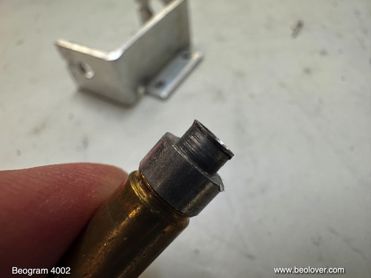
The tube was basically riveted into the orifice in the mounting bracket:
Next time I will probably use a drill to remove the front end of the pressed-in tube before using the arbor press. I installed a new coil made with a 3D printed plastic core:
If you need one, my replacement coils are available via the Beolover Store.
I installed the rebuilt coil assembly into my bench 4002:
I also put in the main PCB that came along with it. Then I plugged my Beogram in, and immediately the coil activated. I quickly unplugged the unit before the coil had a chance to get hot. This behavior suggested a burned through 1IC4, which controls the solenoid current:
I removed the original TIP125 Darlington and replaced it with a stronger TIP107, hoping it will last a bit longer:
This fixed the issue and the Beogram operated normally by lowering the arm at the LP setdown point:


My experience is that most Beogram 4002 and 4004 have issues with their power transistors and I usually replace all of them preventatively when I restore one of these vintage beauties. 
At any rate, this main PCB is again able to control the solenoid! It is time to send everything back to Texas!


Thursday, September 7, 2023

Beogram 4002 (5503): When Disaster Strikes! - Replacement of the Solenoid Switch and Restoration of a Melted Solenoid

Oh well! I recently received a Beogram 4002 (Type 5503) from a customer in Arizona with the indication that 'it does not lower the arm anymore'. I had restored the unit only in Dec. 2022, so this was a bit early for my taste to see it again!

After I removed the aluminum panels it became immediately clear why the arm would not lower again!:

The solenoid had completely melted down! I measured its resistance and it was about 1.2 Ohms. Normally it should have about 9 Ohms. Why this happened also became clear quickly. My solenoid arm extension part did not hold up. It cracked in a very similar way like the original arm extensions:
Because of this weakened arm link the solenoid switch did not get activated anymore and so the solenoid ran at full power even after the arm had been lowered. At some point the insulation of the coil wiring burned off, short circuiting the coil and that was the end of the arm lowering function. 
I extracted the solenoid
and took it apart:
Then I made a new coil. Luckily I recently learned how to do that:
This shows the new solenoid installed in the original bracket:
After I implanted the solenoid I had to realize that it would not activate at full power. This turned my attention to the solenoid switch. I found it to have a too high resistance when closed. And that caused the solenoid to be underpowered. Maybe the switch-terminals also suffered during the solenoid burnout. But it also did not click properly when activating it manually, so there was something wrong with its mechanics, too.
Since these switches are not made anymore, I had to figure out a 'modern replacement'. Immediately, I thought about the end switches used in 3D printers. They have a suitably small form factor, but they usually are only rated for switching DC currents up to an amp or so. Not enough for handling the typical 3-4 Amp current in the Beogram solenoid when it is activating. 
After a bit of thought I decided to try using a power transistor for the 'heavy lifting', and the switch only for activating the transistor. This approach promised reducing the mechanically switched current by about 2 magnitudes since the current gain of such transistors is typically in the 100x range. In other words the switched current promised to only be in the sub-100mA range. 
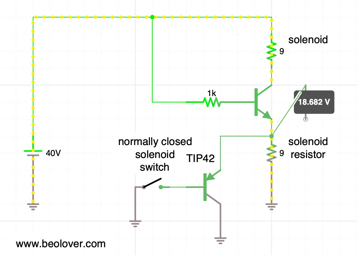
This is the simple circuit that I implemented using a end switch connected as a normally closed switch, so the TIP42 pnp transistor would be on when the solenoid is initially fired up to sink the solenoid directly into ground. This is the situation shown here (yellow beads show the main current flow):
You see that the simulation shows a voltage of about 0.7V at the emitter of the solenoid transistor. This means that the solenoid sees almost 40V driving it with about 4.3 amps based on its approximate 9 Ohms resistance.
After the solenoid activates and pushes its plunger out the solenoid switch gets hit and the TIP42 turns off, sending the current solely though the solenoid resistor. This causes the voltage across the solenoid to be dramatically lowered and with that the current gets reduced:

This situation is maintained during the play of a record when the arm is down.
This shows this concept put into practice on the solenoid switch PCB that I extracted to be able to work on it:
I found the best switch position by trial and error, and then drilled a hole into the circuit board so I could anchor it with a 2mm bolt in place. The TIP42C is bolted in via one of the two mounting screws of the PCB. The way it is connected still allows the board to be be shifted up and down to fine tune the switch position. This is important to make sure the arm hits the switch in a way that it really switches.
The last task was the re-design of my solenoid arm extension. I got rid of the nut and instead used a self-tapping 2mm screw that would put only minimal stress on the plastic. I added a liberal amount of epoxy in the bolt hole and the compartment that receives the end of the metal arm to keep things from separating. This shows the result:
Let's hope this holds up better!
Here you can see the arm in concert with the switch. First with the solenoid off:

And now with the solenoid activated:
Once the solenoid demonstrated to actuate properly, I measured the voltage across it during the activation process. In this measurement the trace corresponds to the signal measured at the collector of the solenoid transistor (0TR4).
But first I measured a reference signal that I was able to obtain conveniently from another 5503 that I have on the bench currently:
Before activation of the solenoid, the voltage at the collector is essentially the same as the power rail, i.e. ~40V. This means the solenoid has 0V across it. Once the solenoid transistor activates, the voltage across the solenoid increases to about 40V and then, after about 10ms, the solenoid arm hits the switch, and the solenoid gets disconnected from ground, and the current flows through the solenoid resistor instead. This results in a strong voltage reduction across the solenoid and it has now only about 8-10V applied to it. This real-life voltage is less compared to the simulation above. I think it comes from the fact that in the simulation I drive the solenoid transistor with an arbitrary 1k resistor connected to 40V, while in the real circuit a series of transistors (TR14/15/16) drives it with a different current.
What really counts is: Does the TIP42 replacement result in a similar behavior as with the original switch? Happily it does as is evident from this trace that I measured on the implemented circuit:
This trace is hardly distinguishable from the standard circuit behavior and so we can conclude that this may be a good fix for broken solenoid switches!
All good again in the arm lowering department of this Beogram 4002! Beolove is sometimes a bit painful, but only steady improvement leads to perfection. And that is what the Beolover aims to achieve!


Friday, August 4, 2023

Beogram 4002 (5503): Repair of a Dead H-Bridge and Some Other Updates

Sadly, an AC-motor Beogram 4002 (Type 5503), which I had restored in early 2020 needed to return to my bench. The reason for the visit was that the carriage would not drive towards the platter anymore. This is usually an indication of a dead power transistor in the H-bridge that drives the carriage motor.

Since the completion of this restoration project I had come to realize that this is a frequent issue with this circuit, and I now routinely replace the H-bridge transistors when I restore a Beogram. Unfortunately, in 2020 I had not grasped yet that there was a 'pattern'. So this Beogram unfortunately had to make the trip back to me to give me a chance to replace these transistors:

Of course I also updated all the other problem components that I learned about since 2020. It is definitely a good idea to replace the power transistors of the push-pull stage of the AC platter motor drive. This shows the original npn/pnp complementary TIP31/32 pair:
I replaced them with stronger TIP41/42s:
Ditto for the solenoid transistor: I replaced the original TIP41
with a higher voltage TIP41C:
This 4002 still had a light bulb set-up in the carriage position sensor assembly. This shows the original components:
I replaced the light bulb with a white LED:
It is important to place the LED not too close to the sensor and approximately 6-7mm above the PCB. Otherwise the 'run-off-stop' mechanism may not work anymore.
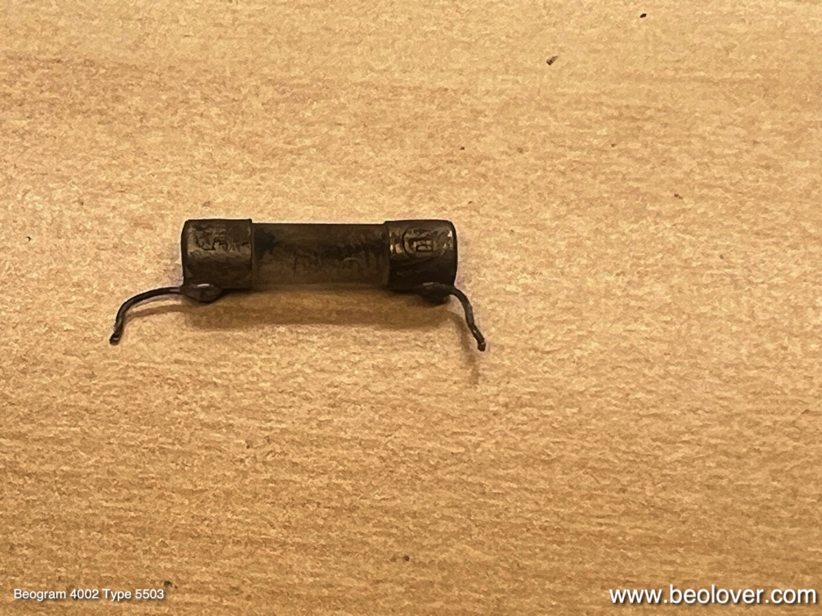
Like many AC-motor Beograms this one also had a 'troubled' fuse F1. It is directly soldered to the PCB. I extracted it:
I measured its resistance, yielding ~13 Ohms. Way too high. So I replaced it with a new one. I had to solder the wires to it:
This shows it implanted:
Another weak point of the AC motor Beograms is the solenoid lever, which came with a riveted plastic extension for activating the solenoid current limiting switch. In all Beograms of this type that I came across so far, the plastic extension developed stress cracks around the rivet:
It is important to fix this since a missing extension will result in an overheated solenoid. I drilled out the rivet, which liberated the extension. This shows the separated parts, as well as my 3D printed replacement ready for bolting on:
This shows the replacement extension in place:
This shows the repaired arm in action. It properly activates the solenoid switch:
Finally, I also replaced the as usual hardened damper gasket with a new one:
This ensures a consistent arm lowering experience. 
This Beogram is now updated to the latest 'Beolover restoration standard'! I will play it for a bit and then it will return to its owner in California.

Wednesday, August 2, 2023

Beogram 4000: Repair of a Cracked Solenoid Arm, Replacement of the Damper Gasket and Re-Glueing of a Plinth Corner

After replacing the wiring sleeve of the carriage harness and repair of an intermittent solenoid this Beogram 4000 needed tying up a few more lose ends before it could be sent back to its owner.

I had originally restored this Beogram 4000 in 2020, and back then I was not aware of some of the 'standard issues' that these decks can develop. One item that learned about in the meantime is the damper gasket. They seem to harden and as a result arm lowering can become erratic causing the arm lowering speed to vary due to random air leaks around the gasket.

This shows the original gasket:

And the new replacement installed:
This Beogram 4000 also came with a solenoid lever that has a plastic extension for activating the solenoid switch:
As I learned over the years from AC motor 4002s, where this type of lever is standard, these attachments tend to break off at the rivet that attaches them to the metal part. This one also already had a hairline crack:
Since it can lead to a fried solenoid when this plastic extension breaks completely off I replaced it with a 3D printed part that I developed for this occasion:
Here a shot from the side:
This shows the lever after re-installation in rest position
and in extended position:
It properly activated the solenoid switch.

In 2020 I also had not realized yet that the BC142/143 power transistors often go out of spec over time. This resulted in occasional carriage drive H-bridge failures, which caused some unhappy returns to my bench. Hence, I started replacing these transistors preventatively in my Beogram projects as a standard feature. I still needed to catch up this Beogram in the transistor department. This shows the original H-bridge transistors:

And with new compatible replacements:
I also replaced the rest of the power transistors:
Finally, this Beogram had a plinth corner that came unglued:
I removed the plinth and glued it back together:
Beolovely! This Beogram 4000 is performing very nicely again. Let's hope it will stay away from my bench for longer this time!