This is the second part of the 'repair report' of the Beogram 4000 that I recently received with an 'oscillating' solenoid and a shredded carriage wiring harness (whose repair is described in the first post).
This post details the work done regarding the oscillating solenoid, and what I learned when it comes to winding your own solenoid coils and how they measure up to the original.
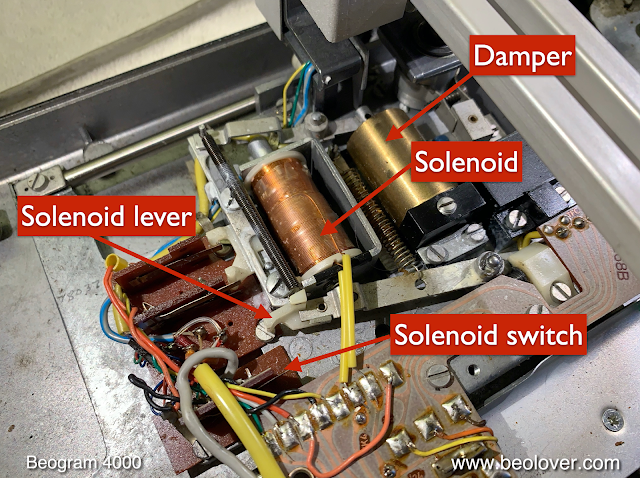
This shows the arm lowering mechanism:
When arm lowering is initiated by the control logic the solenoid pushes the solenoid lever towards the front of the deck. When the lever is fully extended, it also opens the solenoid switch. This reduces the current through the solenoid to a level that is just enough to keep it engaged.
The circuit diagram snippet below shows how this works electronically:
The solenoid is activated by lowering Q1' from 6V to 0V. Via 1R25 and 1D3 this turns off RT10, which in turn activates 1TR11, which then pulls up the base of 0TR4, and the maximum current starts to flow through the solenoid since its lower end is directly connected to GND via the solenoid switch. Once the solenoid has fully activated, the solenoid switch opens forcing the current to flow solely though the solenoid power resistor 7R1, which significantly reduces the current through the solenoid.
Once it is time to lift the arm, Q1' goes high to 6V, and the current through the solenoid ceases to flow, causing it to return to its start position driven by the solenoid return spring. This also closes the solenoid switch again, and therefore the solenoid is ready again for the next time Q1' goes low.
So when a solenoid oscillates, in most cases there is a problem with the GND connection via the solenoid switch: Q1' activates the solenoid, but it does not get enough current and so the return spring drives it back, and then since the spring is slack again, the solenoid extends again and so on...i.e. it oscillates. As my customer put it, this sounds like 'brrrr'!...;-).
Due to this previous experience, I first checked all the connections and wires etc...but it turned out that in this case the wiring and the solenoid switch were o.k. Another indicator that this was not the 'normal' solenoid oscillation was the fact that it only occurred intermittently. A broken wire typically causes this very reliably every time the arm is supposed to be lowered.
Therefore, it was time for a more thorough investigation! First I connected my oscilloscope to the collector of 0TR4 (yellow trace) and to the base of 0TR4 (blue) and measured the 'normal behavior' when the solenoid would not oscillate:
One can see how the base voltage struggles to to go up during the initial current burst, and then after the current settles it reaches its full magnitude.
At this point I was maybe able to induce the 'brrrr' behavior every 50 arm lowering activations or so. Therefore, I pushed the up and down buttons for a while until I finally heard 'brrr', and that is what my automatically triggered measurement showed:
We see that after an initially normal activation, the solenoid then engages in its oscillatory behavior. Since the base of 0TR4 seemed to show a similar pattern as during the initial lowering, I concluded that the oscillation may have been caused by Q1' itself, i.e. the control logic might have been at fault. This was supported by the fact that the initial lowering was executed flawlessly and only after maybe 20ms the next lowering sequence was carried out.
Therefore, I measured the Q1' signal (blue) together with the collector of 0TR4 (yellow). This shows the traces during a normal arm lowering sequence:
We see that Q1' goes low and then the solenoid actuates, followed by an opening of the solenoid switch, which causes a reduction of the voltage at the collector.
After playing with the ups dn down buttons for another while, I finally measured these traces during a 'brrr' moment:
This put my suspicion that the issue may have come from the control system itself at rest. Q1' did not budge during the 'brrr' event! Very good, since a dead logic chip would have expanded this project considerably into new Beogram 4000 territory (so far I never encountered a bad logic chip...). At least, this result told me that the issue must have been triggered by a component or connection after Q1'. So I went ahead and replaced TR10/11/0TR4 as well as the spark snubber diode that is connected across the solenoid leads:
Unfortunately, this did not change anything! After a buch of ups and downs I got the (at this point very dreaded!) 'brrr' again! Very beounlovely!
While poring over all the oscilloscope measurements I had done at various points of the solenoid circuit, it finally dawned on me that the fact that the collector of 0TR4 going to zero during the 'brrr' moments meant that the connection between 0TR4 collector and the top of the solenoid, which is hardwired to ~40V must go open circuit! Since Q1' did not budge during the oscillation events, 0TR4 was continuously on during the events, and therefore the collector did not get pulled up anymore for some reason.
In absence of bad solder joints this basically left the solenoid itself as root cause! I borrowed a solenoid from a Beogram 4004 that I also had on the bench and I exchanged the original solenoid with it:
With this new solenoid in place I was not able anymore to get the oscillation going. And I did spend quite a while pressing up and downs! I measured an interesting curve though with this replacement solenoid:
The yellow trace shows again the collector of 0TR4, and we see that after the actuation of the solenoid, there is a brief dip in the collector voltage after about 5 ms after the arm hits the solenoid switch. I interpret this as a switch bounce due to a mechanical oscillation of the switch terminal. This is supported by the fact that the phenomenon did not always occur, and when it did, the timing was always a bit different. Bouncing is a common phenomenon in mechanical switches. Here it may have been caused by a somewhat different actuation speed of the replacement solenoid.
Since the replacement solenoid belonged to a well-working Beogram where it needed to be reinstalled soon, I decided to make a replacement coil for the original solenoid. The first step was taking it apart. This shows it extracted from the arm lowering mechanism:
The first step is to remove the plunger. The bent extension is screwed into the actual plunger that is moved by the magnetic field.
It can easily be unscrewed using some pliers to hold the plunger (protect the plunger from getting marred using some tape for the jaws) and then turn the extension:
Here you can see the tapped plunger end and the separated extension:
After removal of the locking ring, the next step was pressing out the metal tube that resides inside the solenoid coil core. I did this with an arbor press and a small screwdriver bit to push the tube:
After the tube is out, the coil can be removed:
I drew up a replica of the plastic spool and 3D printed it:
Then I rigged up a stepper motor with two 3D printed centers to hold the spool
And wrote a simple program which would allow me to control the stepper motor speed, as well as counting the turns the motor accumulates during winding of the spool. Then I set out to wind a new coil with 28 gauge 'magnet wire' (which seems very close to the original wire). After a few tries I developed enough skill to be able to get the windings on in a 'homogenous enough' way. The first three layers can be done fairly perfectly by guiding the wire between fingers while the motor turns the spool:
But after many more layers the imperfections pile up and this is how such a coil typically looks like after the spool is full:
My turn counter indicated at this point 956 turns:
I fixated the exit lead with some electrical tape in a similar pattern like the original coils:
Then I trimmed the leads and removed the polyurethane coating of the 'magnet wire' by heating the wire ends up in blobs of solder at the end of the iron tip. After a while the plastic coating evaporates and the wires end up tinned, ready for soldering to pads:
I measured the resistance of this new coil, and I got 8.8 Ohm:
This is very close to the typical ~9 Ohm of these solenoid coils. I re-assembled the solenoid with the new coil and implanted it in the Beogram 4000:
And it worked very well! This proves it does not matter much for this application that the hand-wound coils are not as perfectly wound as the original machine-wound ones. Again I spent some time with ups and downs trying to induce the 'brrr' phenomenon again, but the solenoid consistently performed perfectly.
So I decided to unwind the original coil and have a look:
I used my stepper motor setup to do this since I wanted to count how many turns the wire on the original coil would yield on a hand wound coil. I counted 916:
Pretty close to the coil I made with new wire!
Unfortunately, I was not able to find a break in the wire or other obvious faults, but the coil definitely had gotten hot at some point damaging the spool:
When I measured the resistance of the coil wound with the original wire, it showed only 8 Ohm,
different from the initial measurement of about 9 Ohm. Not sure what this means. So this was a bit disappointing as a result, since I still do not fully know what caused the 'brrr' phenomenon. Based on the oscilloscope traces, the connection between 0TR4 collector and the 40V rail had to be intermittent. In absence of a broken wire this only leaves bad connections between the solenoid and the collector or between the solenoid and the 40V rail. I had checked all this thoroughly during the initial phase of the trouble shooting process and was not able to find anything. So it is all still a bit mysterious! But it seems to work properly now! That is the good part!
Since the resistance measurements didn't show anything really interesting, I decided to compare the inductances of the coils. For this I used my BK Precision 879B LCR meter. The fully assembled 4004 temporary replacement solenoid with the plunger fully in measured about 30mH (at 100 Hz measurement frequency):
Taking the plunger out reduces this to 5.5mH:
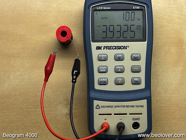
Remove the tube and the bracket and we are left with 3.9mH:
Next I connected 4 coils that I hand-wound from new 28 gauge wire:
They all consistently yielded 3.6-3.9mH, very similar to the working 4004 solenoid.
The coil that I wound with the wire from the suspect 4000 solenoid coil in contrast only yielded 2.98mH, a significantly lower value:
Unfortunately, I did not measure the coil after I removed it for unspooling it. But it seems there may be something different with this wire. Still, the mystery continues...The joys of Beoloving!...;-)


.jpg)
.jpg)
.jpg)


No comments:
Post a Comment
Comments and suggestions are welcome!