This post is a follow up to the initial assessment of a Beogram 4002 that I had received from Texas. It discusses the restoration work done to the unit. This post was a bit delayed by my recent move to Albuquerque, which forced me to focus on a few other things than B&O. But now the dust is settling and the Beolover is back at the bench (when he is not hiking the Sandia Mountains!..;-)
This shows the unit without the aluminum panels:

It was in fairly original condition, which typically makes the restoration an 'uneventful' process in that there are usually only the standard issues that need fixing to get the unit back to like-new operational functionality.
As usual I started out with the DC platter motor:

They usually need their Oilite bearings re-infused with motor oil after having been drained for almost 50 years by operating the deck. To get to the bearings the motor needs to be disassembled:

The bearings are the two small donuts on the black pad. I immersed them into oil and pulled a vacuum. Immediately, strong bubbling started:

This is indicative of air being drawn from the porous bearing material, which makes room for oil to diffuse into the now evacuated pores. This process usually takes 2-3 days. It is done when the bubbling stops. In the meantime I focused on the other restoration tasks.
My first focus was the restoration of the carriage. This picture shows the arm lowering mechanism comprised of solenoid and damper together with a number of linkages that connect everything mechanically:

I removed all relevant parts

for cleaning:

This shows them after 30 min in an ultrasonic cleaner:

Nice and shiny! As usual, I replaced the original damper seal with a new one:

This ensures a consistent arm lowering experience. Then I put everything back together:

There is one more linkage of the arm lowering mechanism that relays the damper movement to the tonearm. This linkage is often stuck. You can see it from the back of the arm assembly. It is the small lever that sits in the "V"-groove of the lever that connects to the tonearm weight assembly:

To get to the pivot point of this linkage, the sensor arm needs to be removed. This shows the sensor arm with removed linkage:

As usual, the small copper pad that helps the arm moving laterally while up came loose after a slight tug with my tweezers. I epoxied it back into place:

After re-installing the linkage the arms needed to be re-aligned properly to be orthogonal to the rods the carriage travels on.

There are two more items on the carriage that usually need attention. One is the practically always cracked plastic pulley

with a precision machined aluminum replacement:

Number two is the replacement of the original tracking sensor light bulb with a LED assembly. This shows the original black bulb housing in place:

This photo shows the bulb housing removed in direct comparison with the Beolover LED assembly. The LED is in the same spot as the filament of the bulb:

I installed the LED assembly:

My next focus was on rebuilding the PCBs. On the main PCB it is best to start with replacing the two power Darlingtons that are installed on the solder side of the board. They are best replaced with the board still bolted in for easy positioning. This shows one of them, IC1, a TIP 120. It serves as voltage regulator for the 21V rail:

When replacing IC with a new modern TIP 120 it can be necessary to put a (yellow) 100nF capacitor across the output to stabilize it:

Without the added capacitor it is possible to get a sizable near-MHz ripple on the 21V rail, which can disable the record detection function. At this point I do not understand why this happens, maybe the current TIP120 devices are faster than the original ones from the 70s, and some kind of feedback loop occurs. I had an interesting afternoon a while ago trying to figure out why a 4002 would not detect records anymore after installing a new TIP120. So I made adding this capacitor part of my standard 4002 repertoire.
After replacing the Darlingtons I removed the board. This show it in its original condition:

And after replacing all electrolytic capacitors, all power transistors, RPM relay and trimmers, as well as the sensor arm transistor:

Then I focused on the output PCB:

There I usually replace the output relay and the capacitor that defines its time constant. I also install a switch that allows tying signal and system grounds together in case there is a hum (especially valuable when using an RCA adapter):

With the boards and the keypad removed it was the perfect moment to tend to the degraded transport lock bushings. Here you can see some of the fragments that are usually spread out throughout the enclosure:

It is a good idea to remove the floating chassis and vacuum out the entire enclosure:

Due to the flat design of the 4002 there is only limited space for the floating chassis to float, and it frequently happens that some of the bushing fragments get lodged underneath the chassis, preventing it from floating properly.
This shows the 3D printed Beolover replacement bushings. They are designed in two parts,

so installation is a snap: Simply put in one half from below and the other from the top and that is it:

After re-installing the floating chassis and re-assembling the locks I replaced the original reservoir capacitor

with a drop-in Beolover replacement:

Next I focused on replacing the last three incandescent bulbs with LED assemblies. First I tended to the RPM adjustment panel. This shows it removed and flipped over, revealing the two covers that conceal the bulbs:

I removed the covers:

This shows the LED replacements together with the removed bulbs:

I installed the LED assemblies. They solder directly to the bulb solder terminals, effectively extending the small PCB with LED circuits:

The bulb covers fit back on without interfering with the LED boards:

The last bulb to replace was the one in the sensor arm. This shows original bulb still installed together with the Beolover LED assembly together with its U-shaped alignment help:

This shows the LED board installed:

On to the adjustments. First I adjusted the tone arm height and made sure it is parallel to the platter across the entire arm sweep. Then it was time to adjust the floating chassis to ensure the platter is flush with the aluminum panels. Once the arm and the platter are in the correct position, the arm weight can be calibrated. I usually calibrate the adjustment wheel to be accurate at the 1.2g set point. The wheel is notorious for being a bit inaccurate across its entire range since it just tensions a spring when it turned. Since most B&O cartridges seem to have the same weight and also are happy with a 1.2g tracking weight it is best to calibrate for this 'sweet spot':

Generally, it is best to measure and adjust the tracking weight occasionally with a digital gauge, regardless of the reading on the adjusting wheel.
The next step was adjusting the arm lowering limit, ensuring that the needle 'misses' the lower sections of the platter ribs by about 1mm:

This will ensure that the needle survives should the arm ever get lowered onto an empty spinning platter due to a malfunction of the record detection circuitry.
Then I adjusted the tracking feedback. The blue potentiometer on the Beolover tracking sensor LED assembly can be helpful for precisely adjusting the feedback:

I also still needed to adjust the bias of the sensor transistor to get 4V at the collector of the transistor:

Then I checked the sensor signal over an empty platter:

A signal that has an amplitude of 5V or greater is sufficient for reliable record detection. This Beogram passed this test with flying colors at ~7V.
The final test was measuring the RPM stability of the restored platter motor. I did this with my Beolover RPM device that can log the RPM in 10s intervals over long periods of time:

This is the curve I measured after about 24 hrs:

This is pretty much as good as it gets with DC motor Beograms! The slight drift is caused by temperature changes. This is an analog control system, and therefore susceptible to temperature change. 1970s technology! But the change is so small that it is not perceptible.
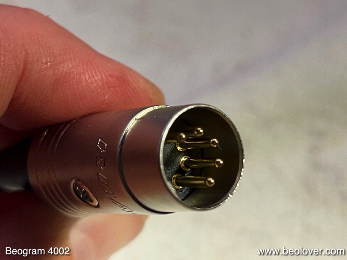
Before giving this deck a test-spin, I still needed to replace the corroded original DIN5 plug:

I installed a nice new all-metal plug with gold plated pins:
One more thing: My customer wanted the Beolover Commander remote control installed. It allows controlling the deck without ever touching the keypad again, which will make its fragile coating last much longer before it needs to be restored. This shows the Commander module installed:

It is a plug-and-play installation in the DC motor 4002 and 4004 Beograms.
And now it was finally time for playing a first record on this restored Beogram! I selected "Discipline" by King Crimson, their first release after the 7 year break. I bought it when it came out in 1981 and I still like it a lot for its high energy and unique prog rock sound. Of course, this record received a thorough ultrasonic clean on a CleanerVinyl ProXL system before I played it.
This shows this nice album together with the fully restored Beogram 4002:

A perfect combination. Very beolovely!
No comments:
Post a Comment
Comments and suggestions are welcome!