This post summarizes the restoration work I did on a Beogram 4002 (5503) that recently arrived from California (initial assessment, see here).
As usual I started out with rebuilding the carriage and arm lowering mechanisms. This shows the solenoid and the damper that actuate the arm lowering:
I removed the relevant parts and cleaned them in an ultrasonic cleaner:
After I re-lubricated and re-assembled everything it was time to do the same for the linkage that connects the damper with the tone arm (it often seizes due to hardened lubricants). This required removing the sensor arm that the linkage could be removed:
As often encountered, the little copper pad that is glued with (these days degrading) double-sided tape to the sensor arm assembly came loose (it helps the arm limit screw to slide along its counter surface):
After I re-assembled the linkage I epoxied the pad back into place:
Now it was time to replace the tracking sensor light source (black box) with a LED based assembly.
I removed the light source, which revealed the aperture that controls the light that falls on the tracking sensor depending on the arm position:
This shows the LED based replacement in comparison with the original incandescent bulb based part. The LED is in the same spot where the filament of the bulb is located:
This shows the LED part installed. The small blue box on-top is a trimmer that allows adjusting the light intensity. That is a great feature for fine-tuning the tracking feedback, which can be difficult to adjust based solely on mechanically adjusting the sensor position:
The final step to restore the carriage mechanism was to replace the cracked plastic pulley
with a precision machined aluminum pulley (provided by a B&O enthusiast in Vienna - let me know if you need one, and I'll be happy to get you in touch):
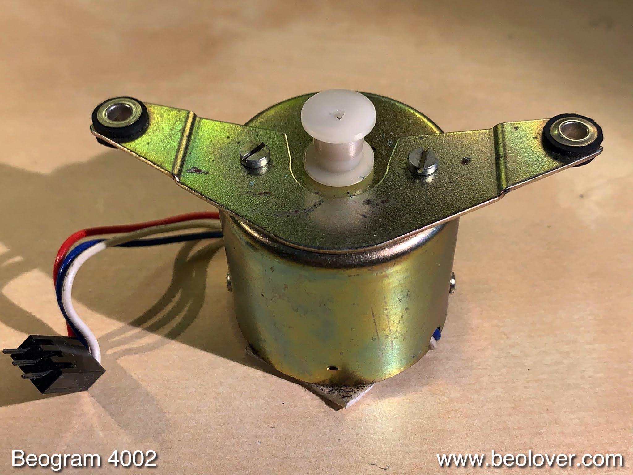
The next step was to replace the original motor and reservoir capacitors, and re-lubricate the AC motor bearings. This shows the original set-up:
I removed everything:
Then I opened up the motor (one has to drill out the rivets that hold the two can halves together). this revealed the two motor coils and the rotor:
I immersed the two can halves with the integrated bearings for 24 hrs in motor oil under vacuum to re-infuse the bearings with oil:
After that was done, I re-assembled the motor. this required replacing the destroyed bearings with screws. To hold the nuts of the adjustment screws in place I developed 3D printed parts:
After bolting the motor back into place (which also holds the 'de-riveted' can-halves together), it was time to install the new capacitor assembly. It is based on a 3D printed holder that organizes the modern, much smaller, capacitors into a neat package that fits under the original mounting strap:
Now I turned my attention to the main PCB. This shows it in its original condition:
I replaced all electrolytic capacitors, and installed modern 25-turn encapsulated RPM adjustment trimmers. This makes adjusting the RPM much more precise and permanent:
Another item that should be replaced in any Beogram 4002 (5503) restoration is the transistor (TR9) that amplifies the record detection sensor signal. It is a high-gain type that is often out of spec these days. I usually replace it with a 2N5089. In order to be able adjusting its collector voltage to 4V as specced in the service manual, R33 that pulls up the base needs to be replaced with a trimmer. I usually instal a 25-turn 5MOhm type, which allows the precise biasing of the transistor:
I usually install it on the solder side first for the above adjustment, and then move it 'below deck' after it is set:
With that new transistor in place it was time to replace the light bulb in the sensor arm with my flex-PCBbased LED replacement. This shows the original light bulb in place together with the flex board that folds into the narrow bulb compartment:
This shows the flex board installed:
This shows the LED source in action. It is based on a warm white LED, which emits enough red photons to illuminate the B&O logo properly giving it its orange-red appearance:
I moved on to the output PCB that harbors the output relay and its delay circuit (to prevent loud noises when the needle sets down in the groove). This shows the original state of the board:
I replaced the relay and installed a switch that allows connecting system and signal grounds (red, behind the blue wire):
Connecting the grounds usually quenches hum issues if RCA plug adapters are used.
After this I moved on to replace the two last incandescent light bulbs, located in this Beogram's RPM adjustment panels. I replaced them with my custom designed LED boards that are based on red/green LEDs tuned to emit incandescent-like light:
I installed them in the RPM panel:
While testing them I realized that the scale background of the 33 RPM trimmer had become wavy over time:
This happens due to the heat emitted from the original light bulb, i.e. is usually found in the 33 trimmer and not in the 45 trimmer since most people mostly play LPs.
I opened the panel up and this shows the wavy background sticker:
I removed it
and replaced it with a cut to size piece of white electrical tape:
This restored the background to a smooth appearance:
While I had the keypad out it was convenient to replace the cracked cabinet guidance washers
with new 3D printed (via selected laser sintering) parts:
I also removed the transport locks to install new lock bushings. The old ones had completely degraded during transport and already ended up in my vacuum cleaner. This shows one of the three locks:
These are the 3D printed (also selective laser sintering) replacement parts:
They are designed in two halves, that install from the bottom
and from the top:
After inserting the bushings it was time to bolt the locks back together:
The next step was to replace the original corroded DIN5 plug
with a new all-metal plug that has gold plated contact pins:
Now I did all the adjustments. After leveling the sub-chassis and adjusting its lateral position with my new adjustment assemblies that attach to the ends of the chassis springs,

I adjusted platter and arm height. Then it was time to set the arm lowering limit. This is an important adjustment since it is the fail-safe should the needle ever accidentally be lowered onto a rotating platter due to a malfunction in the record detection circuit:
Then I adjusted the tracking weight with a digital gauge and calibrated the weight scale to be accurate around the 1-1.2g range (which is where most B&O cartridges need to be):
After this I adjusted the tracking feedback
and then it was time to focus on the 'cosmetics', namely giving the aluminum surfaces a deep clean and replacing the worn keypad
with a refurbished one. This shows the extracted original pad (left) together with the restored replacement that I installed:
And then it was finally time to give this lovely Beogram 4002 a first spin! I recently entered into a bit of a Deodato binge, and I really like listening to his
1978 Album "Love Island" (Warner Bros. BSK 3132), which is very laid back and smooth, perfect for working on Beograms!
Beolovely! I will give this deck a couple more weeks of listening and then it will be time for it to travel back to California.


 After about 24 hrs I plotted the data of this measurement run, which is shown in the blue curve in the graph below:

 I removed the old snubbers,
 and soldered the replacement devices into place:
 Then I put the motor back together and installed it again for another 24 hrs test. That gave me the red curve in the above graph, which did not show any drops anymore.


