Featured Post

Beogram Commander Remote Control: Maybe This is the Final Version!..;-)

This is a follow up to my recent post about the redesigned Beogram Commander remote control board, which now works in both (DC-motor) Beogr...

Monday, January 30, 2023

Beogram 8002 Type 5633: Sensor Checks

Now that the Beogram 8002 is past the electrical restoration and the power supplies check out, I set up for some testing of the various sensor signals the Beogram uses to operate.

Those signals are the platter speed sensor, arm position sensors (there are two) and disc detector sensor. 
All four sensors are optical sensors whose signals the Beogram 8002 microcomputer depends on for operation.

With basic operational tests of the Beogram I can tell that the sensors appear to be doing their job but I like to measure the signals with an oscilloscope to really make sure.

Most of the measurement points can be made right at the microcomputer IC (2IC1) and that is a good place to start as it is the destination of the sensor signals. 

Here are the Beogram 8002 sensor signals I usually look at.


Note that the Disc Detector signal at 2IC1-33 is a two-state signal at this point...meaning that the signal is either at +5V or at 0V, depending on the Disc Detector sensor signal generated on PCB 1.

Here is a portion of the Beogram 8002 schematic that shows the Disc Detector circuit.


Notice the highlighted, yellow circle I placed on the diagram.
That is the node between 1R72 and 1R71 where I measure the raw sensor signal that controls 1TR16 to produce the Disc Detector signal at the microcomputer board.

Here is the probe for that measurement.


I measure the Disc Detector Sensor signal at the 1R72/1R71 node and at 2IC1-33.

I also like to look at the Beogram 8002 "SO" switch state on PCB 1 (P2-1) and at 2IC1 (pin 32).


Here are the oscilloscope measurements at Standby mode and at press Play mode for the SO switch, platter speed sensor and the two arm position sensors.


The sensor signals look healthy so I am pleased with that.
Something to observe about the signals after the Play button is pressed is the empty activity on the two position sensor signals until the SO switch is cleared.

When the Play button is pressed the Beogram 8002 servo motor starts moving the tangential arm assembly towards the platter.  At the same time, the platter drive motor starts rotating the platter.
You can see from the platter sensor signals that the platter speed is ramping up quickly by the change in the sensor signal pulse width.  During that time the tangential arm assembly is still physically in contact with the SO switch, keeping it in the off position. When the tangential arm assembly clears the SO switch, the switch engages and goes to +5V.  That is when the arm position sensors are enabled (have power) and start being counted by the microcomputer (uC) and is how the Beogram 8002 uC keeps track of where the arm position is.
The position counts are how the Beogram knows where the set down points are located, where the end of record position is and where to return to when the Pause function is used.

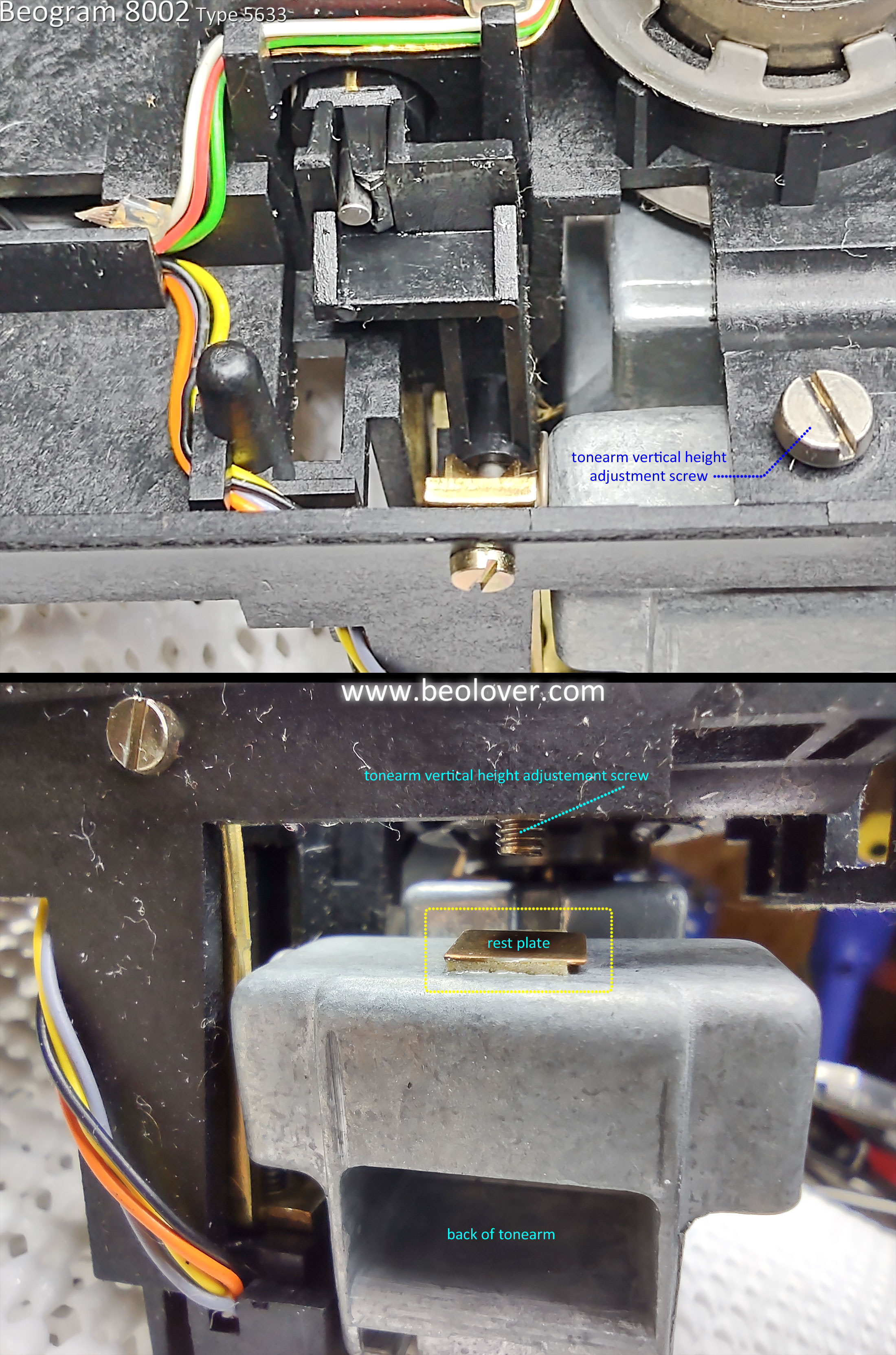
The SO switch location has a mounting screw that allows it to be moved, slightly.  That adjusts the point where the position counter begins and affects where the actual set down point is located.

If a Beogram 8002 loses power during record play, the arm is raised as power to the lowering solenoid is lost.  When power returns to the Beogram, the uC will not know where the arm position is and will return the arm to the Standby position.

Here are the oscilloscope measurements at Standby mode and at press Play mode for the Disc Detector sensor.


The (blue trace in the photo) Disc Detector signal at 2IC1-33 shows how it changes with raw Disc Detector signal at the 1R72/1R71 node (on PCB 1).

During the period before the SO switch is cleared the Disc Detector sensor initializes.  
It is then inactive as the arm moves towards the platter.  The Disc Detector sensor reaches the platter well after the SO switch is cleared and the pulses generated by the sensor lamp reflection off the Beogram 8002 platter cause the Disc Detector signal at 2IC1-33 to go to 0V.  That locks out the Beogram 8002 from lowering the tonearm.

I didn't find any faults with the sensor signals or with operation of the Beogram 8002.
I can move on to the final adjustments to the cartridge tracking force and the record tracking sensor.

Sunday, January 29, 2023

Beogram 4002 (Type 5513): A New Arrival from Florida

I recently received a DC-motor Beogram 4002 (Type 5513)  from a customer in Florida. It arrived in its original box. I extracted the unit and set it up on the bench:

It has pretty good aluminum surfaces, but the keypad has the usual worn keypad coating. This can be alleviated with a rebuilt keypad in exchange. The plinth is in very good condition with nice corners:
I had a look inside. It looks pretty original, except that the motor has been worked on. The pulley is mounted upside down. We will see if this motor can still be restored.
Then I plugged the unit in and pressed START. The carriage started moving and found the set-down for LPs. That was a good sign! The platter motor made the typical dry bearings related shrieking noises.
In summary, this unit should be restorable if the motor is still in a serviceable condition. If not a replacement will need to be found. Stay tuned!


Wednesday, January 25, 2023

Beogram 8002 Type 5633: Initial Power Checks

The Beogram 8002 turntable allows you to connect together the floating chassis with the electronic control boards outside of the cabinet. That makes it easier to test and very convenient.

I used that capability to check out my completed restoration tasks so far.
I wanted to see what works and what doesn't work on this turntable after my initial work.

The first thing to check is the power supply so I assembled the parts and plugged the transformer in to the wall.

Most of the time on this type of restoration I immediately get the little, red Standby dot on the display when I plug in the Beogram for the first time.
In this case, it was blank...but as you can see in the photo, I was measuring the +5V regulator and it does show a proper voltage. 
So this was some connection problem.


Checking the other Beogram 8002 supply voltages I found that everything had power.

Here is the +24V across the 1C27 filter capacitor.


Here is the -24V across the 1C29 filter capacitor.


The 1C24 capacitor measured around 13V that goes to the +5V regulator.


...and the regulated +5V signal to PCB 1 is good.


The problem was that the +5V power was not reaching the 2C28 capacitor on PCB 2.
That wasn't too surprising as connection problems do occur with these turntables.
One item I have never been fond of with the Beogram 8002 (and 8000) design is the PCB 1 P6 connector and ribbon cable to PCB 2.  

It is a press-to-fit connector and often times the ribbon cable does not feel like it mates securely enough.
That was the case here.

Re-seating the cable a couple of times allowed me to finally get the Beogram 8002 to come on in the Standby mode.


I didn't want to leave it like this though.
It would be too easy for the cable to lose a connection again.

I decided to cut away more material from the channel areas of the ribbon cable so I could seat the cable further into the P6 connector.


That worked much better and the cables don't just fall out of the connector like they did before.


Now that the Microcomputer board has proper power I can turn the Beogram 8002 on and check the ±15V regulated supplies.

They both look good.


Moving on, I checked the platter drive and observed that the 33.33 and 45 RPM speeds worked.


I also tested the arm lowering and the solenoid control mechanism appears to work great.


That was just a quick set of tests to see if there are any major problems with the restoration so far.

There doesn't appear to be so I will move on to checking the various sensor signals on the Beogram 8002 and make sure they are working properly.

Monday, January 23, 2023

Beogram 8002 Type 5633: Floating Chassis Restoration Tasks

I wrapped up the work on the Beogram 8002 floating chassis. It should be ready for some functional testing of the turntable operations in the next blog post.

Here is the floating chassis before starting the restoration work on it.


It has a bit of dust as you would expect but nothing major to clean up or repair.

I removed the center hub to inspect the tachodisc and speed sensor.


Next is the disassembly of the tangential arm assembly for inspection, cleaning and lubricating.
I will also check the arm raise/lower solenoid and mechanical parts. 


The arm lower/raise mechanics looked good.
While the arm assembly was turned over I took the opportunity to align the tonearm height with the sensor arm.

Interestingly this Beogram 8002 unit has a little, square rest plate for the tonearm height adjustment screw.  Usually there isn't anything there to keep the screw from contacting the metal back of the tonearm.  That can cause problems with the arm lowering operation so I often have to place a small piece of Dura-Lar plastic there.  In this case, the problem is already taken care of.


Now it is time to clean the old oil and grease from the spindle, rails and attachment pieces.
Then re-lubricate everything and reassembly the arm assembly.


Because this Beogram 8002 was configured for the North America market the rear guide rail has rubber tip ends to dampen any vibrations from the 60 Hz line voltage.

I applied some rubber restoring fluid to the rubber ends when I reassembled the arm assembly.
For re-lubrication of the spindle I still use the original B&O combination of Rocol MTS 1000/2000  with Mobil NUTO H32 mixture. However, a good modern, synthetic oil will also work fine.  Just don't over lubricate the spindle where oil flies off when the spindle spins.  
On the shiny guide rails I apply either some M-kote DX Paste Grease or some Tri Flow Dry Lube.
At the pivot points of the spindle where it attaches to the chassis I use a little bit of Tri Flow Red Grease.


Here is the tangential arm assembly put back together with the tonearm aligned with the sensor arm.


There were a couple of electrical restoration tasks left to do that I didn't complete on the previous post.

One is the replacement of the phono muting relay.
I replaced the original muting relay with one I sourced from Beoparts.


I also installed my usual test connector for adjusting the LDR sensors that are used for the forward and reverse arm scanning operation.  It is kind of a pain to connect DMM probes to make the voltage measurement while adjusting the sensor aperture so I install a three wire test connector that allows checking (and adjusting) the LDRs without opening the Beogram 8002 into its service position.


The Beogram 8002 turntable components can now be assembled and tested.

Wednesday, January 18, 2023

Beogram 8002 Type 5633: Electrical Restoration Tasks

I completed the electrical restoration tasks on this Beogram 8002.
The next step will be the mechanical tasks but first...here is a review of the electrical restoration work.

On the Beogram 8002 restorations a big part of the electrical work is replacing all of the electrolytic capacitors with new capacitors.  

Here is a picture of the main circuit board (PCB 1) with the microcomputer circuit board (PCB 2) before any restoration work was done.


I started with the smaller, PCB 2 assembly.
It only has one electrolytic capacitor, 2C28.  It is a 47uF, 10V electrolytic capacitor.

The Beogram 8002 boards are quite crowded and susceptible to cracks in the solder joints of the board connectors.  For that reason I always reflow the solder joints of the board connectors and on the Microcomputer Board (PCB 2) I replace the socket for the microcomputer IC.

Here is PCB 2 before the restoration.


The next few photos show the removal and restoration of the 2C28 capacitor and the IC socket for the Microcomputer.


I replaced the electrolytic capacitors on the main board (PCB 1) and reflowed the solder on the board connector solder joints next. 


I moved 1C28, a 4.7uF, 63V capacitor to the trace side of the board for more room.  It also required some repair of a PCB trace it uses.


There is one bi-polar, 27uF electrolytic capacitor in the transformer compartment that requires changing.  As the photos show, the original 4C1 capacitor was just over 20% (32.98uF) from the 27uF listed value.  I replaced it with a new capacitor assembly that measures 27.92uF.


The last two electrolytic capacitors I replaced are located on the floating chassis.  They are for the voltage regulator circuit.  There is a 47uF capacitor and a 1uF capacitor that needed replacing.


I can now move on to the mechanical restoration tasks.  Once those are complete I will be ready to test out these electrical updates.

Sunday, January 15, 2023

Beogram 4000: Installation of a Brand New Hood!

The Beogram 4000 that I recently restored also had a scratched hood. Instead of spending 3 hrs in the garage polishing an old hood, my customer sent me a brand new reproduction hood from the Beoparts-shop in Denmark along for installation. These hoods represent a milestone in Beogram 400x restoration. They are manufactured via injection moulding, exactly like the original hoods. This means there are no seams like you find them on hoods made by fusing laser cut panels together.

In short: These hoods look exactly like the original ones. They were developed by Dillen (Beoworld). Their availability has advanced Beogram 400x restorations quite bit. Get your new hood directly from Beoparts-shop or get in touch with the Beolover. I have a bunch in stock in the US.

This post shows how I installed the hood on the original hinge part: Here is very the awesome new hood and a matching aluminum trim:

These hoods come covered with a self-adherent foil to prevent scratching during shipping and installation. I left this foil in place except around the hinge area. 

Let's do it! The first step is to remove the hinge part from the original hood. Usually, one can remove the sides of the aluminum trip with a razor blade:
This allows bending the trim back far enough to get to the often rusty screws:
Simply remove the screws and then take the hinge off:
Then bolt the new hinge in. It has an improved design. The original screws were countersunk flathead type. This creates lateral stress around the bolt holes and is in my opinion the main reason for the frequent cracks that form around the holes, rendering the original hoods obsolete.
The new design uses socket head screws with a thin head. This prevents most of the formation of lateral stress, so there is hope that these hoods may last longer. This shows the bolts in place (don't forget to use the supplied plastic washers under these bolts. This will reduce the stress even further):
Once the hinge has been bolted in, it is time to install the aluminum trim. The key aspect is to apply it precisely centered, that the trim sides reach down to the bottom of the hood on both sides in exact the same way matching the lower edge of the plexiglass. I designed a clip-on part that allows to apply the strip exactly centered. This shows the part for the left end of the strip
and this for the right end. Just place the strip that it exactly matches the ends of the two parts:
I use a small piece of blue painter's tape on the plexiglass to make a small alignment mark on the hood and the strip. Pencil can easily be removed from the brushed aluminum strip:
Using this alignment mark it is a simple task to place the strip exactly centered with the glue down. After pressing the strip into place on top of the hood, I bent the sides down. I realized that it is difficult to properly press the strip-sides into place on the plexiglass, and so I used two clamping tools that I had developed earlier for hinge repairs to press the sides into place for 24 hrs to let the glue bond properly:
I have a mirrored clamp for the other end:
After 24 hrs I took the clamps off. And here we go: A new reproduction hood installed. Beolovely!