Featured Post

Beolover SyncDrive: DC Platter Motor Replacement for Beogram 4002 and 4004 (Type 551x and 552x)

Late Beogram 4002 and the 4004 (Types 551x and 552x), which have DC platter motors instead of the earlier synchronous AC motors usually suff...

Showing posts with label circuit board. Show all posts

Wednesday, January 18, 2023

Beogram 8002 Type 5633: Electrical Restoration Tasks

I completed the electrical restoration tasks on this Beogram 8002.
The next step will be the mechanical tasks but first...here is a review of the electrical restoration work.

On the Beogram 8002 restorations a big part of the electrical work is replacing all of the electrolytic capacitors with new capacitors.  

Here is a picture of the main circuit board (PCB 1) with the microcomputer circuit board (PCB 2) before any restoration work was done.


I started with the smaller, PCB 2 assembly.
It only has one electrolytic capacitor, 2C28.  It is a 47uF, 10V electrolytic capacitor.

The Beogram 8002 boards are quite crowded and susceptible to cracks in the solder joints of the board connectors.  For that reason I always reflow the solder joints of the board connectors and on the Microcomputer Board (PCB 2) I replace the socket for the microcomputer IC.

Here is PCB 2 before the restoration.


The next few photos show the removal and restoration of the 2C28 capacitor and the IC socket for the Microcomputer.


I replaced the electrolytic capacitors on the main board (PCB 1) and reflowed the solder on the board connector solder joints next. 


I moved 1C28, a 4.7uF, 63V capacitor to the trace side of the board for more room.  It also required some repair of a PCB trace it uses.


There is one bi-polar, 27uF electrolytic capacitor in the transformer compartment that requires changing.  As the photos show, the original 4C1 capacitor was just over 20% (32.98uF) from the 27uF listed value.  I replaced it with a new capacitor assembly that measures 27.92uF.


The last two electrolytic capacitors I replaced are located on the floating chassis.  They are for the voltage regulator circuit.  There is a 47uF capacitor and a 1uF capacitor that needed replacing.


I can now move on to the mechanical restoration tasks.  Once those are complete I will be ready to test out these electrical updates.

Saturday, January 7, 2017

Beocord 9000: Replacing Capacitors Wrapped Up

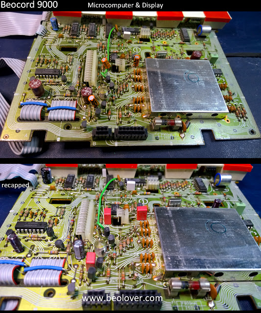
It took a little longer than expected but I am done with the capacitor replacement in this Beocord 9000 cassette deck. As expected most of the capacitors did test within spec. However, a few were out of spec and two were completely bad. On the Microcomputer/Display board there was that 220uF capacitor (C56) that was preventing the Beocord from coming on. Later, on the Dolby board I found another 220uF (C7) of the same brand that was also completely failed. So even though it is quite a big job it is worth checking out all of the electrolytic capacitors.

Here is a picture of the recap work on the Calibration Oscillator Detector board. Just three 1uF capacitors and I replaced them with WIMA MKS type capacitors.


Next is the Microcomputer & Display board. There are not many capacitors here and I will be returning to this board to work on the displays.


Finally, the board with the most capacitors, the Dolby board.


I will clean the slider and Dolby switches with Deoxit while I have this board removed.


Before starting work on the displays I need to check if the Beocord is functioning after the re-capping and re-soldering job. If not, I will have some trouble-shooting to do. So the next step is the re-assembly of the Beocord where I can test it again.

Thursday, January 5, 2017

Beocord 9000: Replacing Capacitors

 Now that it is 2017 and the parties are over it is time to get back to the Beocord 9000 restoration. I started the work replacing the electrolytic capacitors. As I mentioned before, on these Beocord 9000 units it is often the case where very little if any recapping is necessary. This unit appears to have been in storage for quite a while and I already found one bad capacitor so I decided to replace the others.

I typically replace capacitors using audio grade capacitors in the signal path and high reliability, 105°C rated, long lasting capacitors everywhere else. In cases where the capacitor is not in the signal path and is 1uF to 4.7uF, I will often replace the electrolyic capacitor with a WIMA polyester capacitor (MKS). For this recap I removed the Beocord circuit boards so I could inspect and clean them better. I want to examine all of the board connectors closely and reflow the solder joints on them.
The first board is the power supply board.


The next board was the rectifier board.


After that as the Analog/Digital Converter board


Followed by the Record/Playback board.


There were three 10uF electrolytic capacitors on the Record/Playback board that I decided to keep. They measured exactly 10uF and had a lower ESR than new replacements that I had in stock.

Since I am also cleaning the Beocord up as I go I removed the Mic. Amplifier board so I could clean the switch and the plugs while I recapped the small board.


On most of these Beocord units I find a green, sticky substance on the shield wire of audio cables at the connectors. This picture is of a cable with that problem connected to the Mic Amplifier board. I cleaned off the goop and re-soldered the shield wire.


Here is the Mic Amplifier board all cleaned up and ready for re-installation.


I should have the remaining Beocord boards recapped tomorrow.

Saturday, July 28, 2012

Beomaster 8000 Microcomputer PCB Damage

Back to the Beomaster 8000. Today I looked at the missing display segments. First, I thought it is the usual dead LEDs on the boards. The display looked like this:
So I removed the three main displays. Luckily, I decided to plug them into the display 'harness' I made with a breadboard for the last display repairs. Powering them up yielded this:
This is the first Beomaster 8000 display I see that fully works. This told me the problem is elsewhere. I soldered the displays back in and looked at the circuit diagram. The particular LED segments that were out suggested a problem in the drain path to the SN74247 7-segment driver responsible for these segments (IC 2). I checked the signals on plug P-75 and indeed the pins responsible for the c and d segments were at 5V and did not show any strobe signal. This suggested a contact problem. I removed the display board and cleaned the plugs and resoldered the p-75 plug and socket. To no avail. The segments remained dead.
I followed the current path towards the SN74247 and found that the plug pins did not connect to the respective current limiting resistors R21 and R22. This meant that the PCB traces between P-75 and these resistors were broken somewhere. 
A closer look revealed that there had been the same problem at some point in the past with pin 3 as indicated by the white jumper soldered between capacitor and resistor:
I did the same for pins 7 and 8:
This brought the segments back:


The question now is whether to refurbish the displays anyway or leave them as they are.