Featured Post

Beolover SyncDrive: DC Platter Motor Replacement for Beogram 4002 and 4004 (Type 551x and 552x)

Late Beogram 4002 and the 4004 (Types 551x and 552x), which have DC platter motors instead of the earlier synchronous AC motors usually suff...

Showing posts with label display. Show all posts

Sunday, April 22, 2018

Beomaster 6000 (2702) restoration: polishing the red plexiglas display panel

Today was polishing day! The plexi display on this Beomaster 6000 quad had some scratches in it and haziness. Very common after decades of being exposed to (polluted) air, damp, vapours, sigaret smoke, cleaning detergent, bad swiping/dusting, etc. It is very easy to get scratches from finger nails, rings or other jewellery, dirty cleaning clothes, you name it.

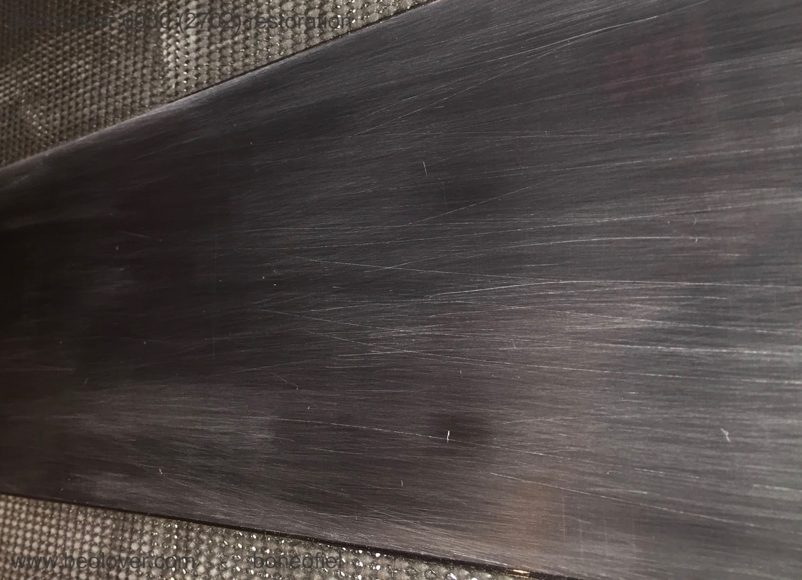
So I started off with 400 grit waterproof sand paper. That revealed the scratches even more as you can see on the picture.


There is only one good way of getting rid of these scratches: polishing, polishing, ...starting with a coarse one and working your way up to a very fine one. I used sandpaper grit 400, 600 and 800 before switching to a micro-mesh type of 1500, 1800, 2400, 3200, 4000, 6000, 8000, 12000.  Please note that "grit" size sandpapers and "mesh" type size are not the same. A standard 800 grit sandpaper correspond to about a 1500 mesh type. Conversion tables can be found on the internet. The Micro-Mesh™ brand has kits available with a whole range of sizes. Micro-Mesh™ likes to call it "a non-abrasive abrasive. It is considered a cushioned abrasive in fact.". It can be washed and reused and has a more structured crystal alignement (compared to ordinary sandpaper) that leaves a more consistent scratch pattern.

Following 2 pictures courtesy of Micro-Mesh™


A few important things to keep in mind when polishing plexiglas:

- polish in straight lines and change direction perpendicularly after each grit/mesh size
- wipe off regularly with a perfectly clean cloth (microfibres of paper towel)
- use a bit of water; it acts as a lubricant, removes dust easier and keeps the plexi cool (in case you want to use a power-tool to do the polishing)

I've done a few Beogram dust hoods, but this display panel seemed to be much more difficult. Not sure why, the material is maybe different, or it's just the fact that this is a dark red (almost black) type of plexi and easier to see scratches.

A few impressions of the different steps in the polishing process:


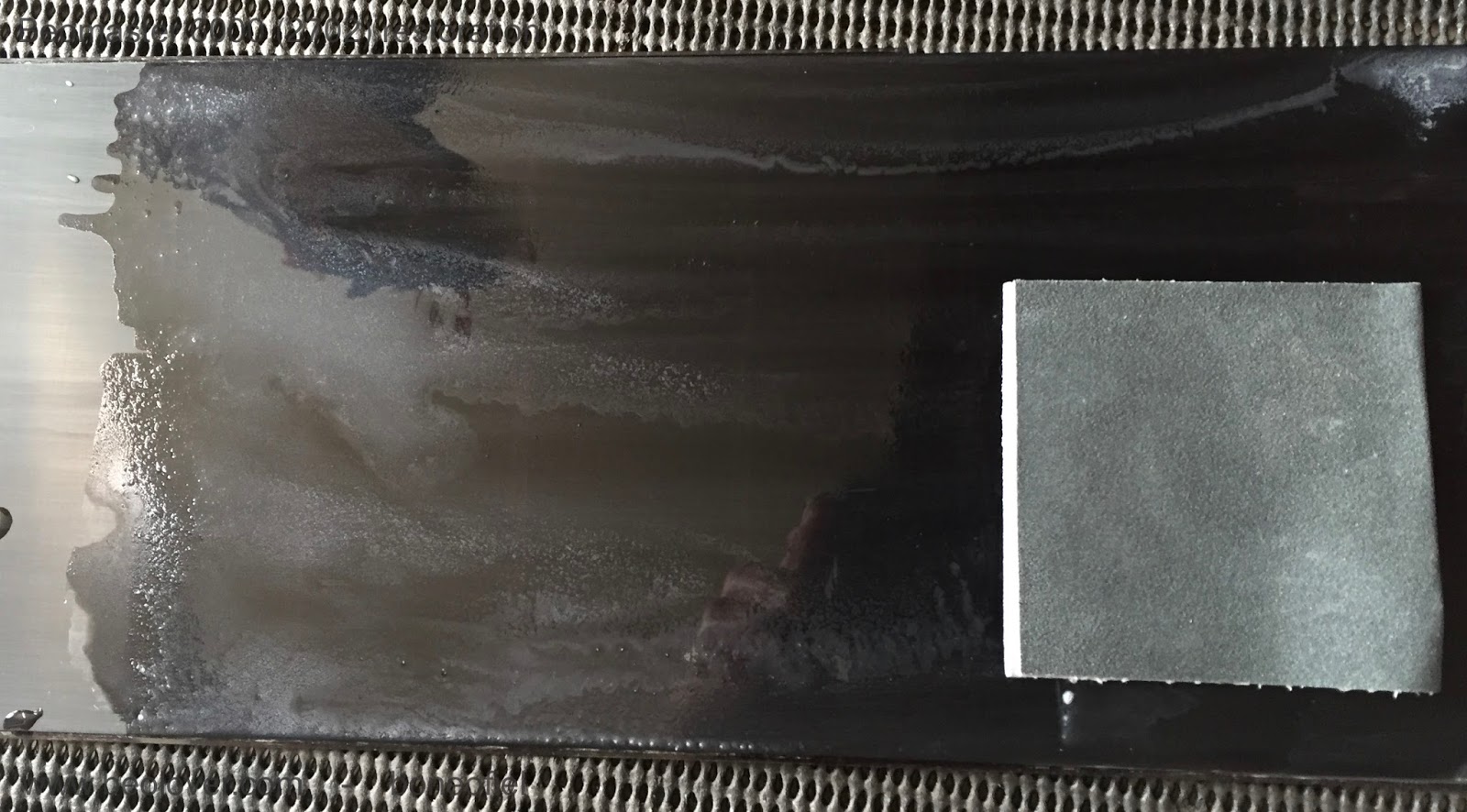
At 2400 mesh I got this result


And already a bit transparent, but still a long way to go.


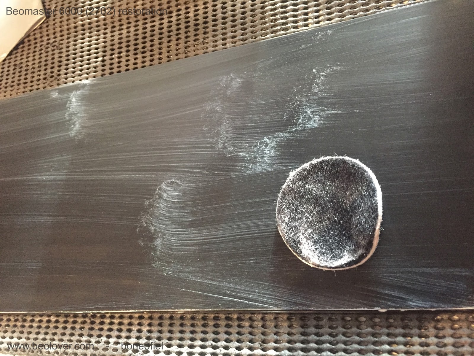
After a few hours I finally got down to Micro-Mesh 12000. Once above 6000 you can hardly call that "sanding" anymore. It's so fine that  you have trouble seeing what the effect is.

The next step is usually a fine Micro Polish liquid that is used, but I wasn't happy with the result at this point. Still to much haziness to my liking. So, I changed strategy and digged out another polishing kit that I used in the past for a car headlight fixture that also had some haziness. The kit contains 2 compounds: a abrasive (cutting) one and a polishing one.


This worked very well. You apply the compound A with a pad (you can use a small polishing machine or drilling tool if you want) for a few minutes. Then wash it off and apply compound B which is ticker and has a brownish color. I used a small pad again and added a few drops of water each time the compound was drying and starting to stick to the plexi. The result was good.


To finish off, I put some surface sealing coating on top to make it water resistant and more easy to clean in the future.


I couldn't resist taking out the restored key panel and the black anodised back frame to put them together with the display to see how it would look like once everything was assembled.


You can see the reflection of some wall pictures (my grandkids..) in the display. Time to rest. I can hardly feel my arms after all this polishing today.....

Thursday, April 19, 2018

Beomaster 8000: Finishing up the capacitor replacement

This Beomaster is getting closer to a test run. I completed the capacitor replacement on all of the boards now. There were no real surprises there. I did find a higher than normal number of capacitors that were out of tolerance and quite a few on the border of being out of tolerance. In addition to the capacitor replacement I also replaced some opamp devices and I reflowed the solder joints on all of the board connectors.

Here are the FM and FM Interface boards.


Next, the preamplifier board.


I had seen quite a bit of dirt, grime and rust on this Beomaster in the previous blog posts so I was wary of possible corrosion on the circuit boards. You can see that the six input level trimmers have some sort of grime on the plastic housing.


Sure enough, several of these trimmer knobs would barely turn. I used two types of Deoxit spray on the trimmers. Each trimmer has three slots that expose the inner workings and I was able to flush the grime and get them working smoothly again.


Along with the capacitor replacement there are seven audio opamp devices that get replaced. Beolover just posted a nice description of why we replace these particular opamps. Here is the preamplifier board with the capacitors removed and new eight pin sockets ready for new LF353N opamps.


...and here is the completed preamplifier board.


The Filter & Tone Controls board also has some audio opamps in the signal path that get replaced. There are also a few capacitors to replace. The tone control sliders and switches also received Deoxit treatment so they operate smoothly and have clean contacts.


As I did on the preamplifier board I added sockets for the new opamps. The sockets are nice because it makes it safer to install the new opamps (no solder heat gets applied to the actual device). Having the socket also makes it easy to switch out a different opamp in the future should that become necessary.


The display and microcomputer boards have only two capacitors each (that get replaced). The display board will be revisited later to change out the display segment LEDs and to replace the four indicator lamps.


Here are the two replacement capacitors on the display board.


This is also just a first visit to the microcomputer board. I will come back to it and replace the two oscillators later.


The 22uF (9C85) capacitor on the left has been replaced before. The original capacitor leads were cut and the replacement capacitor soldered to the remaining leads (still soldered to the board). That isn't necessarily bad but I prefer removing the capacitor and properly soldering in a new one. 

An important thing on this microcomputer board is that some of the component leads must be soldered to both sides of the board. The negative lead of 9C85 is one of those type of components.


The capacitor replacements on this Beomaster 8000 are now all done. I can reinstall the preamplifier, FM, FM Interface, Filter & Tone Controls boards in the Beomaster chassis now and start connecting their cables.


Sunday, April 8, 2018

Beomaster 6000 (2702) restoration: checking, power-up and calibration

Everything is back into the chassis and now it's time to do a last check of all the wiring and powering up. It's important to make sure that no wires have been cracked, became loose or touching the chassis. This may seems obvious, but it is so important in a Beomaster 6000 quad because the space is so tight and most wiring is done with hard wires. I took all the time that I needed and found one wire broken off: a ground connection to the pre-amp.

So, a last peek inside before powering up......


I plugged the unit into my Variac transformer, gently raised the voltage to the required 230V and...........it fired up on all engines! I selected a FM station and listened to Katie Melua's version of Louis Armstrongs "What a wonderful world" ! And indeed it was......

That was a big relief. You never know what will happen after such a big restoration. But, off course, I had tested everything already before putting it al in the main chassis (check here). 

Some final calibration was now needed. I started with the power supply. I had done this before when restoring the power supply PCB, but under load settings may change. I found some slight variation. The +18V had now dropped to +17,85. Not to bad. And the -5V was now -5,1V (not sure why it went up). With the new trimmers in place, it was easy to recalibrate to the correct voltages.


On the same power supply PCB, a trimmer is located to balance the FM reception lights.

The idle (quiescent, bias or no-signal) current was already set before, but I checked it again by measuring the voltage drop over the 2 emitter transistors (0,12 ohm), in series, that are in each set of the Darlington output stages. The service manual describes to measure directly on one of the collector resistors on the PCB. They are very difficult (if not impossible) to reach once the PCB is in place in the subframe. The easiest way is to measure directly on the emitter contacts of both Darlington transistors (PNP and NPN pair) on the cooling elements (white & green wires in below picture). The correct setting in this case is 14,4mV (2x7,2mV). The extra base-emitter current that flows through the emitter resistors together with the collector-emitter current, is neglectable.


Next was the FM bottom voltage adjustment. The manual describes +4,5V. The FM tuner is driven by a variable DC voltage and to make sure that lowest FM frequency is correct and corresponds with the display, this bottom voltage needs to be set correctly.


Another series of adjustment are related to the FM display board with the signal strength meter, the stereo light and the tuning balance lights.


Other calibrations (like the ultrasonic receiver and the Commander remote) have been done before (see here).

Up next is the mounting of the FM display scale and fixing a new dial cord.