Featured Post

Beolover SyncDrive: DC Platter Motor Replacement for Beogram 4002 and 4004 (Type 551x and 552x)

Late Beogram 4002 and the 4004 (Types 551x and 552x), which have DC platter motors instead of the earlier synchronous AC motors usually suff...

Showing posts with label preamplifier. Show all posts

Wednesday, September 30, 2026

Beomaster 8000 Type 1903 - Arizona Restoration Project - A Couple More PCB Restoration Tasks

After the previous post I couldn't stop thinking about the Beomaster 8000 frequency response results.  The output was a little beyond the expected -0.5 dB at the two ends of the 20Hz to 20,000Hz frequency range.  Since the preamplifier board and volume control/filters board of this Beomaster had never been restored, I decided to go ahead and update those two PCBs.

Here is the before and after restoration of the Beomaster 8000 Preamplifier PCB.
The op amp devices and electrolytic capacitors on this board are all in the audio signal path.


I replaced the electrolytic and tantalum capacitors with nonpolarized audio capacitors.  
The op amps were replaced with TI OPA2134 op amps. They are more expensive than the original TL072 and LF353 op amps but the OPA2134 op amp has a very good reputation for usage in audio applications.

The Beomaster 8000 audio signal path leaves the Preamp PCB and goes to the Volume Control/Filters PCB.  The Volume Control circuit is first and the Filters circuit is second.  However, in the Beomaster 8000, the audio filtering (including Bass and Treble) is bypassed by default.  The Filters button inside the metal control panel lid engages and disengages the filtering.

The performance measurements I have been making have been with the filters bypassed.

Here are the before and after photos of the Beomaster 8000 Volume Control and Filters board.


Here is the Beomaster 8000 Volume Control and Filters board after being restored.
Like the op amps in the signal path of the Preamplifier PCB, I used the TI OPA2134 op amps here as well.


Now for the frequency response measurements again.

Quite surprising to me, there doesn't appear to be much improvement.  I was expecting a more noticeable result.

At 20Hz the signal is down just over 0.5 dB.  At 20,000Hz the signal is down about  0.8 dB on the Left Channel and just over 0.5 dB on the Right Channel.

As an FYI, I did adjust the Tape 1 input pots to make sure the Left and Right channel test signals are as identical as possible.


I decided that I needed to look at the frequency response measured at different points in the signal path.

First, just the preamplifier section.
I still kept the input signal source on the Beomaster 8000 Tape 1 source input.
For the output measurement though, I pulled the jumper bars between the Beomaster 8000 External Filter input and output RCA jacks.  This would show me the audio test signal only at the preamplifier stage.

My test cables picked up some noise from the line 60Hz but the frequency response is still very flat.
The output at 20Hz is only down about 0.02 dB and the output at 20,000Hz is only down about 0.04dB.


Next is the Beomaster 8000 Output Amplifier.
I used the Output Amplifier P39 connector for the audio input signal and I measured the output across the 8 ohm, dummy speaker loads.

My test setup encountered much less noise with this measurement.

The Output Amplifier frequency response measurement was also nice and flat.
At 20Hz the output is only down about 0.2dB while at 20,000Hz the output is only down about 0.05dB.


The Preamplifier and Output Amplifier boards checked out very flat as I would expect.

That means the Volume Control and Filters board must be the affecting the frequency response measurement I get with the end to end test.

Here is the Left Channel frequency response with the audio input at P27 of the Volume Control and Filters PCB and the output measured at P24.

Again, my test setup picks up the line 60Hz but you can see how much different the shape of the frequency response is.


I hadn't looked at just measuring the Volume Control and Filters board by itself before so I spent a little extra time.  Because the capacitors and op amps are all new and known good components, I wondered about the AD7110 (logdac) IC device itself which performs the Beomaster 8000 volume control functions.

Instead of jumping in and replacing the volume control devices (there is an AD7110 IC for each channel), I decided to take advantage of having a couple of spare Volume Control and Filter boards available.

Both of my other (restored) Volume Control and Filter boards yielded very similar frequency response waveforms.  It would appear that is a characteristic of this volume control design...but I will need to measure more Beomaster 8000 units to confirm or refute that.

For now, this as far as I will take this experiment.  The frequency response results I am getting are very close to the -0.5dB range specified in the Beomaster 8000 technical data sheet.  More importantly, the music output of this Beomaster 8000 sounds very good as things currently stand.  So I will start putting components back into place inside the Beomaster 8000 cabinet and do some final listening tests before shipping this receiver back.  

I have several more Beomaster 8000 units to restore so I will definitely be repeating these measurements for comparison.

Wednesday, November 15, 2023

Quad 33 Preamplifier: A B&O Project Diversion

Here is a quick non-B&O project that diverted my attention recently :-)

I did not know about Quad and the (famous) Quad 33 preamplifier growing up.  It wasn't until I started working on Bang & Olufsen (vintage) audio components that I became aware of the Quad 33.  A number of vintage B&O collectors I know also like Quad audio components so that created my interest.

Recently, I decided to dive in and check one out.  Currently, here in 2023, used, unrestored Quad 33 preamplifiers can be found in the $200 USD range.  That's not bad and quite affordable when you hear one.  Now that I have heard it I can see why it is popular.  It sounds great.

Here is the Quad 33 as I received it.


The first thing that jumped out at me is how nice it looks.
It is a smart, clean design and it is very compact compared to other preamplifiers.  Especially when the Quad 33 came out ... 1967 !

I love how the rear panel input and output jacks label what the (DIN) pins are.  That is great.
The Quad 33 uses 5 pin DIN jacks for the audio inputs and a 4 pin DIN jack for the preamplifier audio output signal.  The 5 pin DIN inputs match what the Bang & Olufsen source components provide (i.e. Beogram and Beocord cable plugs).  The 4 pin DIN audio output jack is not commonly found but plugs for those are available at places like Mouser.

The design of the Quad 33 preamplifier also provided a way for an owner to change the input gains for the Tape input/output and the Disc (phono) input.

That is done using removable/changeable boards in the back of the Quad 33 cabinet.


Here is the Quad 33 with its outer cover removed.


I have the primary preamplifier boards outlined in the photo above.
Starting on the left is the Disc (turntable) board (M12019).  It is the phono preamp with the RIAA functionality.

Next to the Disc board is the Power Supply (M12032).  It includes the transformer and is switched on and off by a power switch built into the back of the volume control.

On the far right are two preamplifier boards (M12017).  One for each channel (left and right).

One of the first things to check on a used Quad 33 preamplifier component is the Balance slider control that is just under the volume control (on the front panel).  It turns out that it is very common for the mechanical control mechanism to have broken ... and no longer work.

That was the case with mine.

These next few photos show my Quad 33 with the front panel removed and the repair of the Balance control.

The problem that occurs is that the Balance potentiometer starts to bind and becomes difficult to turn.
That puts pressure on a plastic fork piece that is the mechanical control of the Balance control.
Eventually the pressure is too much and the fork breaks off rendering the control mechanism non-functional.  The next photo shows a disassembled Balance control with a broken fork.


The round post on the Control Lever is supposed to rest in the gap of the two-pronged, plastic fork.
As you can see, one side (prong) of the fork is no longer there.

My repair for the broken fork was to design and make a 3D printed part that would just snap over the remaining fork part of the control.  One reason for that is the white, plastic fork piece is glued into the Balance slide control.

Here is the 3D part ready to be fit onto the Balance slider.


... and here is the 3D part installed.  I just snapped it in place without glue.  I plan to leave it like that and glue it in later if that becomes necessary.


The above photo showing the repair of the broken, plastic fork also shows a different 1kΩ (linear) Balance potentiometer installed.

The repair of the fork corrected the broken mechanical part of the Balance Control but it doesn't fix the problem that caused it.  That was the original Balance potentiometer that started to bind (stiffen up).

I took Balance potentiometer apart and cleaned it with Deoxit. That made a big difference and the potentiometer became easy to turn again.  Note: Initially it would not turn without the aid of pliers !


After reassembling the potentiometer I measured to see that it was functioning.  It was.
However, the control did not feel smooth.

So I decided to replace the potentiometer with a modern Bourns 1kΩ potentiometer.

The replacement potentiometer is very smooth and quiet.  The barrel of the control fit perfectly through the mounting hole.  The only issue was that the shaft of the control was a little bit long to fit behind the Quad 33 front panel.

Instead of cutting the metal control shaft off (to fit), I decided to just design and print another 3D part to act as a spacer.  I designed the spacer to support the potentiometer key so I still had a mounting key.

Here is the new Bourns potentiometer and mounting spacer installed.


Moving on from the Balance control repair I performed some capacitor replacement tasks.
That was to replace the old electrolytic capacitors in the Quad 33 with new electrolytic capacitors.

Here are the Quad 33 areas where I replaced electrolytic capacitors.
Pretty minimal compared to my other recent audio restoration projects.


Here are the boards after the capacitor replacement.


I won't show it but I also did some Deoxit cleaning on the other Quad 33 potentiometers (volume and filter controls) as well as the pushbutton switches.

At this point I reassembled the Quad 33 and tested it with a Quad 405 (current dumping) power amplifier that I also recently acquired.  The Quad 405 power amplifier only required a few capacitors replaced on each output amplifier board and nothing else.

To my disappointment, the Quad 33 did not power up.

That took me to the second mechanical switch repair that had to be performed.

It turns out that a failed Quad 33 power switch is not uncommon either.

Here is the problem I discovered after trouble-shooting, then opening up the Quad 33 power switch.


As you can see in the highlighted sections of the photo above, there are worn areas of the power switch contacts caused by arcing when the contacts close.

The Quad 33 itself doesn't require a lot of power so my theory is that power switch wear like this more likely occurs when other electrical components are plugged in to the two AC line accessory jacks at the rear of the Quad 33 cabinet.  Something like a power amplifier that also gets turned on when the Quad 33 is turned on would cause much more current to pass across the Quad 33 power switch contacts.

In any case, my power switch was faulty and I had to repair it.

One option was to just connect the fused AC line input directly to the Quad 33 transformer and not use the power switch.  In that case the Quad 33 could be plugged into a nice surge protection device that has a power switch.

I wanted to have the Quad 33 Volume/Power Switch work though ... so I opted to attempt a repair.

It was not very easy as it turned out.
As you can see in the first photo of the disassembled power switch above, I was able to open it up.
That required carefully prying out the round phenolic switch contact board from the black, plastic housing.

From there I filed and cleaned the switch contacts.  That was pretty easy.

The power switch reassembly is where the difficulty was.
Maybe there is some neat trick to it but I didn't find one.

The main problem is to keep the switch components in place when the phenolic switch contact board is mated back into the housing.  The metal spring mechanism presents the biggest challenge because it has to connect to a part on the switch contact board and to a part on the housing ... plus, the spring is fighting the attempt to do that.

After quite a few unsuccessful tries I decided to use some thick damping grease that I use on my B&O projects (for damping lids closing).  

The damping grease is so thick that it kept the switch components from moving when I mated the switch contact board back into the housing (and maneuvering the spring in to place).

Here is the reassembled power switch.


In case you are wondering ... yes, that is a spare Volume Control/Power Switch in the background.
Its power switch has the same failure.

Although the contact switch assembly fit back into the housing snuggly,  I didn't trust that it would remain that way with just friction so I used some JB Weld epoxy to seal the deal.

Here is a photo of the Volume Control/Power Switch re-installed in the Quad 33.
In looking at the Quad 33 schematic that came with the preamplifier, I could see that the Volume Control/Power Switch assembly (both of mine) is missing a safety capacitor across the contacts that power is applied to.


I found out from another Quad 33 owner that has a working unit that the missing part (SKF24R) is a 0.042uF + 100Ω safety capacitor.  I used this one from Mouser.


That took me to attempt number two of listening to music with the Quad 33.


The audio was quite good ... when there was sound :-(

I was experiencing a channel dropout whenever I operated a switch on the Quad 33 front panel.  So obviously, there was some sort of bad connection going on there.

I couldn't visually inspect and see the problem so I reasoned that I needed to disassemble and clean all of the front panel switches.  That would give me piece of mind that the switches were indeed, clean.
The exercise of touching all of the switches would give me a chance to go over all of the solder joints too.

So off I went on another switch repair exercise.

The worst part of the pushbutton switch cleaning was getting to them.
I did have to remove a lot of the inner components of the Quad 33.


I removed the switch assembly for the stereo and source selection.  It solders to a "motherboard" of the Quad 33 plus it has a small, interconnect board that solders on the top of it.  So it required complete de-soldering and removing to clean.


On the switch assembly for the Quad 33 filters, I decided I could clean them without removing the assembly from the Quad 33.


Removing and opening up the pushbutton switches for cleaning was surprisingly easy.  Easy compared to the switch assembly of a Beomaster 3000, 4000 or 4400 amplifier.

The main thing is to be in control of the individual switch when the spring is released.  You don't want parts ejected across the room.  Keeping control of the switch is pretty easy though :-).

The switches are freed up from their respective switch holder assemblies by carefully lifting up metal tabs and removing three metal clips that group sets of switches together.  For example the stereo and mono switches make up one switch group.  The source selection make up another switch group and, of course, the filter buttons are a switch group.


Even though the switches are the same mechanical switch design, their assemblies are slightly different depending on the number of contacts in the switch.

Here is one of the largest switches, the filter cancel button.


By first pulling the button spring back and releasing the front of the white, plastic clip ...


... the white plastic clip can be slid towards the back and lifted out.
WARNING: Removing the clip is what fully releases the spring.  So the technique is the hold the pushbutton assembly together with one hand while removing the white, plastic clip with the other.
With the clip removed, you can slowly let go of the pushbutton assembly so the switch can be pulled apart without the spring causing any problem.

Oh yeah, pull the switch part with the spring loaded contacts out of the switch with the switch situated with the bottom side up (as shown in the next photo).


I used Deoxit on the contacts (with the tiny springs) and on the contacts inside the switch housing.
My cleaning tools were a small brush and a foam pad.


Reassembly of the switch is just the reverse of the disassembly of course.

Some of the pushbutton switches do not have the white, plastic clip that is removed.
Instead, they have a built in plastic tab that must be lifted to allow the switch to be disassembled.
Take care to keep the pushbutton assembly under control as the tab is released.


I cleaned all of the switches the same way.

Overall, the task was not bad and went quickly.  I was careful on each switch to make sure I was always in control of the spring.

I reassembled the Quad 33 for the third time.


Finally, the Quad 33 is fully operational.


I did test it again with the Quad 405 power amplifier and a pair of Beovox MC 120.2 speakers.
It sounded very good and there are no glitches in sound.  
Whatever it was, cleaning the switches or re-soldering all of the board joints, the channel dropout problem is gone.

My next step was to build a preamplifier to power amplifier cable I could use with another power amplifier (other than the Quad 405 amplifier).

I used a Switchcraft 4-pin DIN plug and a pair of female RCA plugs to make the cable.


I will now test this wonderful little preamplifier with some other power amplifiers I own and do some music listening tests before doing any electronic measurements on the bench. 

Friday, May 8, 2020

Beomaster 4400 Type 2419: Checking the amplifier right and left channels

Before I finish reassembling this Beomaster 4400 receiver I made a few amplifier measurements to make sure the left and right channels are close to each other in their audio performance.

My testing methods cannot be the same as what Bang & Olufsen used back in the seventies so I am not looking to hit those same performance measurement values. The goal of my performance tests are to make sure the left and right channels perform the same...or at least very close to each other and that they are similar to other Beomaster 4400 units that have come across my workbench.. If one channel is way off the mark from the other on the same test then I have to figure there is something wrong.

The tests I like to use in comparing the channels are a Total Harmonic Distortion (THD) test on the output amplifier sections and the preamplifier sections. For that I use a QuantAsylum A401 Audio Analyzer to generate a 1Vrms sine wave test signal at 1KHz. That signal goes into the Beomaster 4400 Tape 1 source input. I measure the output at the preamplifier outputs then again at the output amplifier outputs (across an 8Ω dummy speaker load). It is actually an 8.08Ω load as I use a 0.08Ω series resistor as a sense load to make the measurements with the QA401 analyzer.

Here is the Beomaster 4400 connected up for testing.


The distortion measurements through the preamplifier were very good as expected.


So were the power amplifier outputs.


The frequency response measurements were also good. These tests are made using a frequency response plugin that is part of the QA401 Audio Analyzer. It executes a series of pulses at different frequencies and measures the output. The stimulus is still Tape 1 and the output is measured across the 0.08Ω dummy speaker load. When the test is complete the QA401 plots the output.

The end points (20Hz and 20KHz) are in the 1.0dB to 1.8dB range of the flat line which is pretty typical with this test setup. Both channels measure the same.


Satisfied with the electrical work so far, I will continue on with reassembling the Beomaster 4400 now and then some functional testing with all of the source inputs and listening tests of course.  Those are the most enjoyable tests to perform :-).

Monday, July 15, 2019

Beomaster 8000 - Workbench Unit - Investigating FM source audio in the Phono source channel

In this post I wanted to revisit Beolover's fix for reported FM audio crosstalk in the Phono channels.
I actually have been checking for that fault in my Beomaster 8000 restorations and with these new source switching IC device replacements. Unfortunately I had been unsuccessful in replicating the problem.

To review the problem...
Make sure the turntable connected to the Beomaster 8000 does not have a vinyl record ready to play.
When the Beomaster 8000 is switched on from Standby to Phono the Beomaster 8000 volume can be cranked up without hearing any music from the Phono music source.  That is good and is what is expected.

Next switch the Beomaster selected source to an FM station (preferably a strong station). Note the music that is selected. Now switch back to the Phono source (again with no record playing). Turn the Beomaster 8000 volume up and you can begin hearing (faintly) the FM station that you were just on bleeding into the Phono channel.  That is the problem.

As I mentioned, I had not been able to create this problem until this weekend when I moved my workshop Beomaster 8000 unit to a different bench and connected up a powered Terc FM antenna to the radio antenna input. This produced the strongest FM signal I had seen on the Beomaster. Retesting the FM crosstalk problem...I now had reproduced it.

Interestingly this test setup is with my new analog switch devices installed in the Beomaster 8000 preamplifier board. The preamplifier board also has TI OPA2134PA OpAmp devices for all of the analog sources.


Up until now I had reasoned that any audio crosstalk must be occurring in the analog switches the Beomaster 8000 preamp board uses. That made the most sense. However, this preamp board has the new multiplexer switching devices that have very good audio specs and low crosstalk ratings. I thought that should take care of any audio source crosstalk.

It turns out that it doesn't and that is quite surprising...and I do not understand the source of the problem at this point.

An acceptable work around for someone not wanting to make any wiring changes is to always put the Beomaster in Standby mode prior to selecting the Phono source. That will keep the FM tuner in the Beomaster muted while using the Phono source.

We want our cake and eat it too though so I decided to implement Beolover's fix for this problem.

I performed the same wiring modification Beolover came up with but I implemented the change differently.  I wanted to be able to easily switch from the original wiring to the modified wiring.  That option will allow me to keep investigating the problem.

My implementation is to put female jumper connectors on the two wiring routes related to this problem and fix.  Beolover's fix is to run the FM board audio mute control line to the preamplifier board phono source selection line. When Phono is selected on the Beomaster control panel the phono source selection line will tell the FM board to mute the FM audio. When the phono source is deselected the FM control will unmute the FM audio.

Here is the modified wiring for this on the FM board. The picture shows the FM audio mute control line connected to the default path the Beomaster 8000 originally takes.


The yellow wire from the FM board 1R37 resistor can be disconnected from the default ground path and connected to the Preamp board added connector (also on a yellow wire).


This path routes the FM audio mute control line to the preamp board Phono source selection control line.


Testing this modification in the workbench Beomaster 8000 unit I verified that I get no FM audio at all in the Phono channel with I have the FM audio mute control line connected to the preamp board.  I also verified that moving the FM audio mute control line back to the default position re-introduces the FM crosstalk problem.


Monday, July 8, 2019

Beomaster 8000 - Workbench Unit - Testing a replacement device for the AD 10/192 Multiplex Switch on the preamplifier board

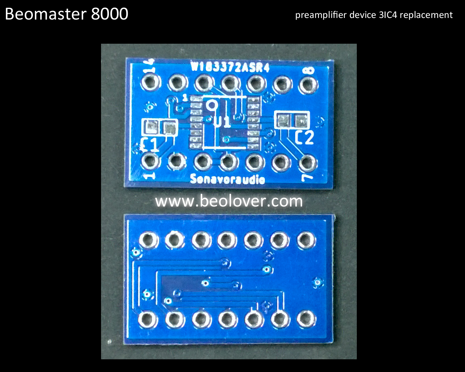
To go together with the previous Beomaster 8000 replacement part for the preamplifier source switching device (AD 10/278 - 3IC102/3IC202), I have completed the replacement part for the other switching device on the preamplifier board.

The second source switching device is 3IC4. The original device is an AD 10/192 multiplexer and like the other switching ICs, this device is no longer available.

Here is the schematic diagram again that shows the two source switching type devices in the Beomaster 8000 preamplifier.


The 3IC102 and 3IC202 replacements were completed earlier. Now it is time for the 3IC4 device.
Like the the other replacement I first built a prototype and tested it in my Beomaster 8000 workshop test unit. It worked as good as I expected so I had an adapter board made.


Here is the replacement switching device on the new adapter board next to my prototype.


...and here is the first replacement device unit installed in the Beomaster 8000 preamplifier.


The Beomaster 8000 preamplifier works great with the source multiplexing devices replacements.
Now to the fun listening test phase.