Featured Post

Beolover SyncDrive: DC Platter Motor Replacement for Beogram 4002 and 4004 (Type 551x and 552x)

Late Beogram 4002 and the 4004 (Types 551x and 552x), which have DC platter motors instead of the earlier synchronous AC motors usually suff...

Wednesday, March 20, 2024

Beolover SyncDrive: DC Platter Motor Replacement for Beogram 4002 and 4004 (Type 551x and 552x)

Late Beogram 4002 and the 4004 (Types 551x and 552x), which have DC platter motors instead of the earlier synchronous AC motors usually suffer from dry motor bearings and/or bad spark snubbers. This often causes very noticeable RPM variations that ruin the listening experience. These motors can be restored by oil-infusing under vacuum, but even when restored, they do not measure up to the original AC platter motors or the later linear drives in the Beogram 8000 and 8002. Often there is significant RPM drift due to temperature variations and other environmental influences, and the analog feedback-based RPM control circuit causes fairly strong wow and flutter compared to the AC-motor Types and the 8000 series.

Once I realized the relative inferiority of the DC drive a few years ago (and also being slightly annoyed by restoring one DC platter motor after another..;-), I started working on an adequate replacement for these motors. I desired an upgrade for DC Type Beograms that would make them as good as the other models. This took me on a long and pretty interesting journey exploring different motor types and control approaches.

I finally settled on a brushless three-phase motor. The motor in the final design is custom manufactured for best performance and it is synchronously driven. The control system is able to measure the actual RPM of the platter, which enabled an auto-calibration feature that allows precise RPM adjustment.

I made a (rather long...sorry!...;-) video that explains the in and outs of the SyncDrive, demonstrates installation, use and gives a discussion of its performance relative to the other Beograms of the day. Enjoy:


The SyncDrive is available via the Beolover Store. Send an email to beolover@gmail.com if you are interested/have questions.

If you rather read than watch: Here is a short summary of the most important aspects:

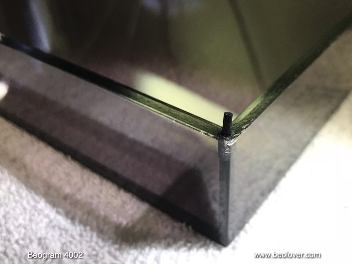
The SyncDrive is an easy plug-and-play installation without the need for soldering (see video below). This is how the SyncDrive looks installed in lieu of the original motor:
The board bolts directly to the mounting posts of the original DC motor, and the electrical connections are made by a single wire harness that connects to the main board:

This picture indicates the essential features of the SyncDrive:
The speed sensor measures the platter speed from below, using the platter ribs in the same way the BeoloverRPM device uses them from above.
The user interface is activated by pressing any of the four buttons while the platter rotates. Once pressed, the indicator LEDs come alive and the interface is ready to interact. The buttons allow automatic calibration of the RPM and manual adjustment (33 and 45 are independently adjusted/calibrated depending on the actually selected RPM of the Beogram). Furthermore, the influence of the RPM panel above the keypad can be deactivated if desired. This can be useful if there are issues with the potentiometers in this panel, or if accidental RPM change is to be prevented.

I characterized the performance of the SyncDrive using the BeoloverRPM device, which allows precise RPM measurements and log them over time. 
This shows a direct wow and flutter comparison between a restored DC-motor and the SyncDrive:
The measurement covers about 60 turns of the platter. The 'noise' in these spectra is caused by small variations of the spacing between the platter ribs. Since the BeoloverRPM device measures the time between the passing of ribs under its sensor, slight variations of the spacing introduce a measurement artifact. The two shown measurements were performed in the same Beogram with the same platter, i.e. have the exact same platter pattern. This allows a direct comparison. The red curve was measured with the SyncDrive installed, while the blue curve was measured with a restored original DC motor. The 'beating' pattern of the blue curve is an indication of the analog control system acting to keep the RPM constant. In essence, the RPM of the original motor 'meanders' around the 33.33 set point in an attempt to stay close. All feedback based control systems operate that way: The actual RPM is compared with the setpoint, and when the RPM is too low, the motor speeds up until it is measured too high, then the process reverses. This causes a wavy trajectory of the actual RPM around the set RPM. The art of feedback systems is basically to keep such variations at a minimum. The analog control system of the 4002 does a pretty decent job, but it is no match for the precision of synchronous motors, which do not rely on feedback, but rather on a very stable oscillator that determines the RPM top-down, and the motor simply 'obeys'. Precise oscillations can be generated with high accuracy, which makes such motors superior as platter motors.

This can be clearly seen when comparing the performance of the earlier AC platter motors found in Beogram 4002 550x Types and the original 4000. This graph shows the above two curves in comparison with a curve measured on a restored Beogram 4000, as well as the later 8000 and 8002 types:


The pink curve was measured on the 4000. It is clear that the performance is much better than the DC motor, which is a direct result of the synchronous operation of the can stack AC motor of the 4000, which is driven by an analog Wien precision oscillator. The slight waviness of the curve is most likely the result of the elastic coupling between the motor pulley and the platter causing a weak 'jo-jo effect'.
It is interesting to compare the performance of the belt drives with the later linear motors of the Beogram 8000 and 8002. Sonavor kindly contributed the green curves when I sent him the redesigned BeoloverRPM for testing. The overall RPM stability seems very similar to the 4000 and the SyncDrive. This is interesting since the linear drive in the 800x is a feedback based system. Here we see that feedback does not need to be bad if it is well designed. The linear drive benefits from the absence of a belt, which takes the elastic coupling out of the equation. A digital control system coupled with high-resolution feedback from an ~80 slots tacho disk seems to be sufficient for a fairly precise control that is much better than what was achieved with the analog control of DC motors. It is interesting to compare the two green curves: The much smoother 'platter pattern' of the 8002 is a result of its different platter design: The earlier 8000 still used a 4002 style platter, and consequently its platter pattern is similar to the measurements on the 400x. The (likely) etched platter of the 8002 seems to have more smoothly varying spacings between the platter ribs. I do not know how they really made these platters, but the smooth variations suggest a projection aberration during pattern generation for the etching process.

It is satisfying to see that the SyncDrive is matching up fairly well with the early 4000 and the later 800x.
When it comes to long-term stability the SyncDrive is actually better than the early 4000:

While the 4000 has a much better wow and flutter than the DC motor 4002, it has similarly strong longterm RPM drift. This is not a surprise, since its Wien oscillator is analog, and therefore also more easily affected by temperature variations. The SyncDrive compares favorably with a much smaller drift, courtesy of its digital control system. Unfortunately, we were not able to perform such measurements on Beogram 8000 and 8002s (yet!...;-). They shut down after 30 min if they recognize that no record is being played. I suspect that their RPM stability is also pretty good due to their digital control system.

In summary, I think the SyncDrive turned out to be a nice upgrade for any DC-motor Beogram, bringing them to AC-motor Beogram level (and likely even 8000 and 8002 level in terms of RPM stability).


Tuesday, March 12, 2024

Beogram 5500 Type 5943: Operational Again

This Beogram 5500 turntable is playing records again.  I connected it to its Beomaster 5500 unit and fitted it with an MMC-2 phono cartridge.


The Beogram sounds great and the remote control functionality with the Beomaster works perfect.
These Beosystem 5500 components are ready to return home to their owner.

To get to this point from the previous post I had to go through the Beogram 5500 service manual adjustments.

The set down point and the platter speeds were the only adjustments that were out of range on this turntable.  However, there was a problem with the platter motor making an audible racket as it turned.
The sound is similar to Beogram 4002/4004 platter motors as they age and their oilite bearings dry out.
I am not setup to re-infuse the bearings right now the way Beolover restores the Beogram 4002/4004 motors. I will save this motor for restoration later and in the meantime use a spare Beogram 5500 platter motor.


Bang & Olufsen used this same 12VDC MMX-4H2RPB motor as the platter motor for a number of their turntables.  Both tangential arm and radial arm turntables from around 1984 and on. 

The replacement motor is nice and quiet so the platter rotates silently now.

For the speed adjustments there are two trimmer resistors on the Beogram 5500 controller board.


To check the speed setting I used the new Beolover RPM tool.
In order to put the Beogram 5500 into record play mode so I could measure the platter speeds I placed a 45 RPM record on the platter then paused record play.  The 45 RPM record leaves the edges of the platter with the markings exposed for the Beolover RPM tool to measure with.


The tonearm set down point for record sizes 17 cm (~7 inch) and 30 cm (~12 inch) were initially off the mark on this Beogram.  

The service manual specifies that the 17 cm set down point should be adjusted first, then the 30 cm set down point.


For the 17 cm set down point adjustment there is a black, plastic eccentric disc that moves the set down position in or out as shown in the following picture. The disc can be rotated with a flat head screwdriver.


For the 30 cm set down point adjustment there is a metal lever whose position is moved with a white, plastic (nylon) adjustment screw.  After the position is moved, a locking screw is tightened to ensure the lever position doesn't change.


Here is the 30 cm set down point after the adjustment.


Although I didn't have to adjust the Beogram 5500 record tracking sensitivity it is worth noting that I checked it.
That adjustment appears more difficult on this type of Beogram than the Beogram 400x and 800x turntables. On those turntables it is easy to disable the platter motor function and move the arm to a test track where the arm is lowered.  Once lowered, the platter is manually rotated to check the record tracking.

On the Beogram 5500 while the platter drive can easily be disabled by removing the platter belt, manually getting the arm to a test track to test the sensing of the arm position seemed difficult.
Manual operating the platter to control the arm movement and set down are rather unclear.

For this Beogram 5500 I put on a test record with the platter functional and observed the record tracking by viewing the servo motor advancement from the rear of the Beogram.


From this vantage point I was able to check platter revolutions with regard to the Servo Motor advancing the drive pulley.

I could see that this Beogram Servo Motor started advancing the arm within 2 turns of the platter after the initial set down. That is setting down on a music track...not setting down on the lead in groove.
Once set down, the Servo Motor advanced the arm every revolution of the platter.

The rest of the adjustments like the audio signal muting, arm alignments and suspension were all good so I was comfortable to install a good MMC-2 phono cartridge for the listening test.

Tuesday, March 5, 2024

Beogram 4002 (5513): Full Restoration and a Test Spin with George Duke

This post describes the restoration of a Beogram 4002 that I recently received from a customer in Texas. My initial assessment of the unit is posted here.

This shows the unit with the aluminum panels removed. It was in original condition, a perfect starting point for a functional restoration:

As usual, I started with the DC platter motor, they all need their Oilite bearings re-infused with oil. This shows the extracted motor:
I disassembled it to get to the bearings. They are the two small donuts on the black pad upfront:
I immersed them in oil and pulled a vacuum. Immediately strong bubbling started:
This bubbling is a sign that the vacuum draws the air from the empty porous bearing material. This makes room for fresh oil to diffuse into the material. Oilite bearings work by releasing minute amounts of oil from their pores onto the shaft while the motor is running. Unfortunately, this means that they have a finite life/runtime.
The infusion process usually takes 2-3 days. In the meantime, I focused on the rest of the Beogram. 
The next step was the restoration of the mechanical carriage systems, the arm lowering mechanism and the  components that allow moving the carriage itself. This shows all the parts still in place:
I took everything apart. It is a good idea to rest the carriage on a soft support pad while the rods and spindle are removed to protect the fragile wiring on the bottom of the assembly:
This shows the old lubricant encrusted parts ready for the ultrasonic cleaner:
Nice and shiny after an hour in the cleaner:
Then I began to reassemble everything. It is important to put a new gasket into the damper plunger:
This ensures that the arm lowering speed is consistent. The original gaskets have a tendency to occasionally cause the arm to drop un-dampened, which can be a harrowing moment (especially when a new $600 cartridge is mounted...;-).
Unfortunately, the spindle nut holder broke apart in the ultrasonic cleaner. They are frequently cracked due to overtightened screws. Luckily, the Beolover has a replacement part, which is shown here next to the broken original:
Here it is shown installed. It uses the original screw:
This shows the re-assembled arm lowering mechanism:
I also installed a new precision-machined aluminum carriage pulley to replace the original cracked plastic unit:
Now it was time to look into the damper-to-arm linkage, which is often also stuck due to hardened lubricants. It is located between the tone- and sensor arm assemblies, and mounted on the sensor arm side. You can see it here sticking out in the V-groove that is on the link mounted on the back of the counterweight assembly:
To get to the pivot point for cleaning and re-lubrication, the sensor arm needs to be removed. This shows the assembly out and the linkage removed:
Make sure you do not loose the small spring that is under the locking washer if you try this at home.
While I worked on this I also checked the small copper plate that eases the lateral arm movement when the arm is up. It is only attached with double sided tape and came off easily:
I cleaned the tape off and glued it back into place with epoxy:
The final step on the carriage was the replacement of the original incandescent bulb in the tracking sensor with a Beolover LED assembly. This shows the original black bulb housing still in place:
I removed the bulb housing, which revealed the aperture that regulates the light on the photo sensor depending on the arm alignment:
This shows the original bulb together with the Beolover LED assembly:
This shows it installed:
Next I removed the RPM panel above the keypad. This shows it extracted and flipped over, revealing the bulb housings:
I removed the covers. The bulbs are located in the small aluminum parts that hold them in place::
This shows the removed bulbs together with the Beolover LED assemblies that solder directly to the bulb solder points:
I soldered them into place:
They are basically extensions of the PCB:
The bulb covers can be re-installed, the LED boards do not obstruct them:
Next in line were the PCBs. I started with the main board. This board has two power transistors mounted on the solder-side. It is best to replace them with the board still in place since their heatsinks need to be aligned with the mounting holes of the board. This shows IC1, which is usually a TIP120: 
I usually replace it with a TIP102 with is a stronger version. The modern replacements need a 100nF capacitor between the emitter and ground to quench some strange high-frequency oscillations that can cause the record detection circuitry to malfunction. The cap is the small yellow component above the transistor:
I also replaced IC4 with a TIP107 and moved on to the component side of the board. Unfortunately, I forgot to take a picture of the original state of the board. I only took one of the 'RPM section', which consists of the RPM relay and the master RPM trimmers to the left:
As usual I replaced all electrolytic capacitors, power transistors, the relay and the RPM trimmers, and the high-gain transistor in the record detection circuit (they often have reduced gain, which can imperil the record detection function). This shows the board with the new components installed:
Here a detail shot of the rebuilt RPM section with a Beolover replacement relay and modern 25-turn trimmers for precise RPM adjustment:
Then I moved on to the output board. This shows the original relay and capacitor still in place:
I replaced the relay with a Beolover replacement and put in a new capacitor. I also installed a (red) switch that allows connecting system and signal grounds in case there is a hum issue:
At this point it was time to clear out the enclosure since this unit had completely deteriorated transport lock bushings. First I removed the original deal-capacitance main capacitor:
Then it was time to take the entire floating chassis assembly out. This is done by removing the transport locks:
This shows the naked enclosure:
An impression of the remains of the original transport lock bushings:
Luckily, there is a Beolover replacement part for these. This shows the three replacement bushings:
They install very easily due to their two-component design. This shows one of the 'empty' bushings receptacles:
With one half of a new bushing installed
and completed with the other:
Here an impression how it looks with the locking bolt in place:
And on the way to the reassembly of the lock:
This shows the completed lock:
This Beogram also had lost its original plinth guiding washers. Someone replaced them with regular shoulder washers, which is an emergency solution at best:
The original washers are eccentric, which allows adjusting the lateral position of the plinth a bit. This shows the Beolover replacements:
They are made from resilient Nylon for smooth movement of the plinth:
There was still one light bulb left that needed to be replaced, the one in the sensor arm. This shows the small compartment at the end of the arm pulled out. You can see the bulb in place. Next to it is the Beolover LED assembly that replaces the bulb together with its alignment aid:
I removed the bulb and installed the LED board:
Then I put in a new reservoir capacitor. Since double-capacitance units like the original unit are not made anymore, I used a replacement assembly composed of a 3D printed adapter in which two standard capacitors are mounted:
Next I focused on repairing the off-switch on the carriage position detector board. It had lost its plastic extension. This prevented this Beogram from turning off properly when the carriage was in home position:
To repair this issue, it is best to remove the PCB:
This shows the other switch on this board which still sported the plastic part:
A while ago I designed small Beolover 3D printed replacements:
They are glued on with epoxy and restore the original functionality:
This deck still had another issue which needed to be addressed: One of the mounting pieces that hold the RPM panel in place had cracked. This happens when the RPM panel is pried out at an angle:
Luckily there are reproductions available at the Beoparts-shop in Denmark. All you need to do is remove the springs from the original cracked part
and transfer them to the new one:
After this was settled it was time to do the mechanical adjustments. First I adjusted the platter to be at the proper distance to the arms and parallel to their motion path. The next step was adjusting the floating chassis to yield a platter flush with the aluminum panels. This can take a few iterations since there is only little leeway for these adjustments due to the elegant flat design of the Beograms.
Once these basic adjustments are achieved, the arm lowering limit can be adjusted:
The needle should be about 1 mm above the lower segments of the platter ribs when the arm is lowered. An important safeguard to protect the needle should the arm ever be lowered due to a sensor malfunction.
Next came the adjustment of the tracking feedback:
Then I adjusted the bias of the sensor transistor to the specified 4V:
After moving the adjusted trimmer to the component side, I checked the sensor response with the oscilloscope. This is the signal obtained at the collector of the sensor transistor:
The amplitude should be close to 5V. This sensor performed very well.

At this point the bubbling of the oil infusing bearings had finally stopped, so I extracted them from the oil
and put them back into the motor. After installing the restored motor into the Beogram it was time to do a 24 hrs RPM stability test with the new BeoloverRPM device:
In its 'slow' mode, the BeoloverRPM allows logging the RPM in 10s installments for long periods of time, which is perfect for detecting intermittent RPM inconsistencies.
This is a graph of the 24 hrs measurement:
This result is pretty much as good as it gets with DC motor 4002s. The slow longterm drift is a result of temperature changes that affect the feedback circuitry.

In 'fast' mode the BeoloverRPM device shows the raw data and one can see the typical repeating 'platter pattern' that is a result of the small distance variations between the platter ribs, i.e. the pattern repeats every 24 data points:
This measurement artifact is the main reason for the noise observed in the longterm spectra.
A fast-mode measurement covering about 47 platter rotations also reveals the action of the feedback mechanism that keeps the RPM constant:
The beating pattern is a result of the superposition between the repeating 'platter pattern' and sinusoidal RPM changes caused by the feedback system. Beating phenomena occur when two waves of slightly different frequencies interfere with each other, creating a periodic variation known as a 'beat'. In this case it means that the feedback system varies the RPM a bit slower than the platter rotation. All feedback controlled brushed DC motors operate in this way, i.e. control electronics correct the speed based on an RPM measurement. When the motor is too slow, the voltage is increased a bit, causing it to accelerate, and when it is too fast the voltage is reduced causing a slowdown. This results in a periodic variation of the RPM. Optimization of the feedback circuit tries to minimize the ups and downs, but they can not be completely eliminated.
After this excursions into physics it was time to replace the somewhat messy original DIN5 plug:
I installed a nice new all-metal plug with gold plated contact pins:
Beolovely! And finally it was time for a test spin of this restored Beogram 4002! I selected one of my favorite records, "The Aura Will Prevail" by George Duke. He recorded this for the German MPS label in 1975. Of course this lovely vintage album was cleaned ultrasonically on a CleanerVinyl ProXL setup, which removed most crackling and restored its sound to its original glory. 
A perfect combination! As expected this Beogram played the record perfectly!
Next came the restoration of the hood, which needed an in-depth polishing:
I sanded it down with 400 grit paper until all the scratches were evened out:
Then I polished it back with ever finer girt until it was nice and shiny again:
The final step was installing new rubber bumpers ensuring a solid 'plop' when the hood is dropped onto the plinth. First I drilled out the remnants of the original bumpers:
Then I glued snippets of a 2 mm O-ring into the holes
and trimmed them to 1 mm length after the glue was dried:

And this concluded the restoration of this lovely Beogram 4002! I will now play it for 1-2 weeks to make sure it has no intermittent issues. Then it will be time to send it back to its owner in Texas!