Featured Post

Beolover SyncDrive: DC Platter Motor Replacement for Beogram 4002 and 4004 (Type 551x and 552x)

Late Beogram 4002 and the 4004 (Types 551x and 552x), which have DC platter motors instead of the earlier synchronous AC motors usually suff...

Showing posts with label Beosystem 5500. Show all posts

Tuesday, March 12, 2024

Beogram 5500 Type 5943: Operational Again

This Beogram 5500 turntable is playing records again.  I connected it to its Beomaster 5500 unit and fitted it with an MMC-2 phono cartridge.


The Beogram sounds great and the remote control functionality with the Beomaster works perfect.
These Beosystem 5500 components are ready to return home to their owner.

To get to this point from the previous post I had to go through the Beogram 5500 service manual adjustments.

The set down point and the platter speeds were the only adjustments that were out of range on this turntable.  However, there was a problem with the platter motor making an audible racket as it turned.
The sound is similar to Beogram 4002/4004 platter motors as they age and their oilite bearings dry out.
I am not setup to re-infuse the bearings right now the way Beolover restores the Beogram 4002/4004 motors. I will save this motor for restoration later and in the meantime use a spare Beogram 5500 platter motor.


Bang & Olufsen used this same 12VDC MMX-4H2RPB motor as the platter motor for a number of their turntables.  Both tangential arm and radial arm turntables from around 1984 and on. 

The replacement motor is nice and quiet so the platter rotates silently now.

For the speed adjustments there are two trimmer resistors on the Beogram 5500 controller board.


To check the speed setting I used the new Beolover RPM tool.
In order to put the Beogram 5500 into record play mode so I could measure the platter speeds I placed a 45 RPM record on the platter then paused record play.  The 45 RPM record leaves the edges of the platter with the markings exposed for the Beolover RPM tool to measure with.


The tonearm set down point for record sizes 17 cm (~7 inch) and 30 cm (~12 inch) were initially off the mark on this Beogram.  

The service manual specifies that the 17 cm set down point should be adjusted first, then the 30 cm set down point.


For the 17 cm set down point adjustment there is a black, plastic eccentric disc that moves the set down position in or out as shown in the following picture. The disc can be rotated with a flat head screwdriver.


For the 30 cm set down point adjustment there is a metal lever whose position is moved with a white, plastic (nylon) adjustment screw.  After the position is moved, a locking screw is tightened to ensure the lever position doesn't change.


Here is the 30 cm set down point after the adjustment.


Although I didn't have to adjust the Beogram 5500 record tracking sensitivity it is worth noting that I checked it.
That adjustment appears more difficult on this type of Beogram than the Beogram 400x and 800x turntables. On those turntables it is easy to disable the platter motor function and move the arm to a test track where the arm is lowered.  Once lowered, the platter is manually rotated to check the record tracking.

On the Beogram 5500 while the platter drive can easily be disabled by removing the platter belt, manually getting the arm to a test track to test the sensing of the arm position seemed difficult.
Manual operating the platter to control the arm movement and set down are rather unclear.

For this Beogram 5500 I put on a test record with the platter functional and observed the record tracking by viewing the servo motor advancement from the rear of the Beogram.


From this vantage point I was able to check platter revolutions with regard to the Servo Motor advancing the drive pulley.

I could see that this Beogram Servo Motor started advancing the arm within 2 turns of the platter after the initial set down. That is setting down on a music track...not setting down on the lead in groove.
Once set down, the Servo Motor advanced the arm every revolution of the platter.

The rest of the adjustments like the audio signal muting, arm alignments and suspension were all good so I was comfortable to install a good MMC-2 phono cartridge for the listening test.

Tuesday, March 5, 2024

Beogram 5500 Type 5943: Replacing the Transport Chassis 1106 Base

 In order to get this Beogram 5500 functional again the bottom part of the tangential arm assembly chassis (1106) must be replaced.

At the end of the previous post I showed photos of this Beogram 5500 chassis and the photos revealed a broken tab necessary for the arm control string to connect to.  Without that tab the Beogram 5500 tangential arm assembly cannot operate.

The first step in replacing the bottom section of chassis 1106 is to remove the arm assembly from the guide rails.

There are two rails that I lifted up on one end and slid out to remove.


A view of the back of the arm assembly shows a spring (for arm lowering and raising) that will have to be removed.


Having removed the guide rails, the tangential arm assembly can be lifted and turned to access other parts that will have to be disassembled.

A nice part about this design is that the phono audio cables can be detached from the base of the arm assembly without having to de-solder or disturb the phono cable connections.

As this photo shows, the phono cables are fitted around the chassis 1106 base so they just need to be maneuvered out of their slots.


There are also two screws at the base of the chassis that must be removed so the bottom piece of 1106 can be removed.


...and here is the tangential arm assembly ready for the bottom (white piece) to be pulled off.

You can see that the phono cables are out of the way.


Here is the bottom piece of chassis 1106 removed.


Again, here are the old and the replacement chassis 1106 bottom pieces to show the mounting tab for the tangential arm guide string.


Reassembly with the new arm assembly base was just the reverse steps of the assembly.

With the proper chassis 1106 base installed it was easy to attach the tangential arm guide string.


I installed a new servo belt and tested that the tangential arm assembly is operational.


The set down points of the tonearm for 17 cm and 30 cm records are a little off.
I will be going through the service manual adjustments for this Beogram 5500 next.

Sunday, March 3, 2024

Beogram 5500 Type 5943: As Received

 I recently opened up and examined a Beogram 5500 turntable audio component that goes with this Beomaster 5500 restoration I did earlier.

This Beogram 5500 does not function and appears to be dead.


Opening it into the service position I immediately saw a problem with the tangential arm assembly drive...the drive string was not connected.


Both ends of the drive string are disconnected and a bit tangled.


After sorting the drive string out and began to re-install it, I discovered a problem with the common mounting post for the two ends (Point H in the service manual diagram).


Mounting post "H" is missing.


It might be possible to make some sort of replacement but I do happen to have a parts unit Beogram 3000 Type 5903. It is in really bad shape and beyond restoration consideration. However, its internal parts are in good shape.

Bang & Olufsen used this same internal Beogram assembly on quite a number of their tangential turntables (including the Beogram 3000 and 5500).  I should be able take the white, plastic tangential arm assembly chassis (1106) from the Beogram 3000 and use it in the Beogram 5500.

Here is a photo of the Beogram 3000 arm drive mount on its 1106 chassis.
It clearly shows the missing mounting post "H".


On a positive note, I discovered this Beogram 5500 has a blown main fuse.
Replacing it got the turntable to turn on again and its motors run.

Sunday, October 22, 2023

Beomaster 5500 Type 2333: Reassembly and Initial Testing

The previous project post showed the dis-assembly of the Beomaster 5500 for doing work on the circuit boards.

That post left off with the output amplifier heatsinks needing to be re-installed on the Power Supply & Output Amplifier board.

I used Sil-Pad thermal insulators in place of thermal paste as it is easier to work with (less messy) and does a great job.  There are two lone transistors (IC205 and IC405) that fit between the heatsink channels that do require some thermal paste compound as they don't have spring clips to press them against the heatsink (like the other, larger transistors do).


The next set of pictures show the re-assembly of the restored boards back into the Beomaster 5500 cabinet.


With the circuit boards re-installed I was able to plug the Beomaster 5500 into AC power and do some initial tests on the Beomaster.

I did some quick measurements of key DC voltages with the Beomaster turned on.
The positive and negative 40 volt rail voltages were there as well as 5 volts, 8 volts, 12 volts, 13 volts and 28 volts.

I adjusted the Left and Right channel no-load current biasing for the Output Amplifiers and then tried playing some music with the Beomaster.

Here are photos of my measurement probes for the the no-load current adjustments.
That adjustment requires the Beomaster 5500 to be on (out of Standby), have the volume level of the amplifier set to zero and no speakers connected to the amplifier.


The trimmers were adjusted so the voltage reading across the emitter resistors of the channel measured 11 millivolts DC.

The Beomaster 5500 was now ready for a quick listening test.
When the voltages check out and the no-load (idle) current has been adjusted, I like to do a listening check of the amplifier.  It is like an early reward for the restoration work to get to this point.

I connected up two sets of Beovox speakers in the workshop.  A pair of MC120.2 speakers and a pair of S-55 speakers.  For a music audio source I connected an iPod to the Beomaster 5500 CD source input.


The Beomaster 5500 sounds great (as expected).
Now I can complete the rest of the Beomaster 5500 reassembly and move on to some audio tests.
I will also be doing some functional testing of this Beomaster 5500 with other Beosystem 5500 components and the MCP remote control.

Wednesday, October 11, 2023

Beomaster 5500 Type 2333: PCB Restoration Tasks

In the previous post I assessed the restoration tasks of this Beomaster 5500.

This post shows the work performed on the Beomaster 5500 circuit boards.

The first step was to remove the boards that will need to be worked on.
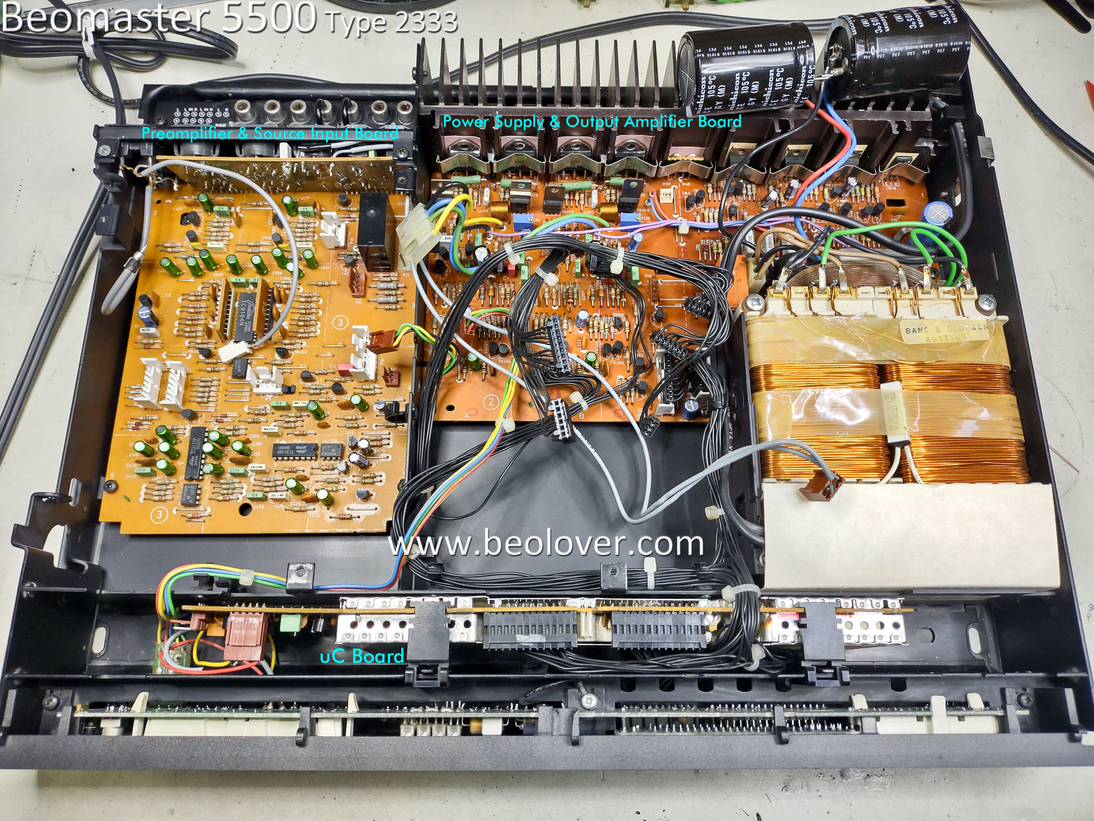
Here is a photo of the Beomaster 5500 prior to removing the boards.  The boards that will be worked on are labeled in the photo.


The following pictures are a sequence of Beomaster 5500 photos showing the boards being removed.


The last photo above shows the Microcomputer board removed...so I will start with that one.
Here are the before and after pictures of the Microcomputer board restoration.
There are just two electrolytic capacitors in this board.
There is also a CR2430, 3V Lithium battery.  It still measured 3V but it is still good to go ahead and replace the battery with a brand new one.


Note that for installing the new CR2430 battery I installed a battery holder for it.


The next board assembly is the Cooling Fan assembly.  It also has two electrolytic capacitors that I replaced.


The FM board came next.

Here is the FM board as it was received.


Here is the FM board after the electrolytic capacitors were replaced.


Here is the recapped Preamplifier board.  I didn't take a stand-alone before recapping photo of it so here are a couple of after recapping photos.  I replaced all of the signal path electrolytic capacitors with non-polarized, Nichicon audio capacitors.

Note that the highlighted Muting Relay had already been replaced so I didn't change that component.


The last Beomaster 5500 circuit board I worked on is the Power Supply and Output Amplifier board.
Here it is removed from the cabinet prior to any restoration work.


The white thermal compound on the heatsink assembly is just getting to the point where it feels a little bit dry.  For that reason I decided to remove the heatsink, clean the old thermal paste off and put new thermal protection on during re-assembly.

Here are photos of the heatsink removal and thermal paste cleanup.


Here is the Power Supply and Output Amplifier after I replaced the electrolytic capacitors, power supply relay and trimmer resistors for the output transistor bias.
There are two signal path blocking capacitors (2.2uF) for the audio signal from the Preamplifier board to this board.  I replaced those two capacitors with the same type I used in the signal path on the Preamplifier board.


Here is a closer photo of the new trimmer resistors.


The original power supply relay looked like this, de-soldered from the board.


The relay (RL1) still works but judging by the heat marks on the board and the fact that the Muting Relay (same type of relay) was already replaced...it is a good idea to go ahead and replace this relay.

I used a modern, enclosed relay.  It has two extra relay contacts that I had to cut off so that I end up with an identical mounting foot print.  I have used this replacement relay before on my own Beomaster 5500 and Beomaster 5000 amplifiers so I know it works well.


The next steps are to re-install the output amplifier board heatsink assembly then re-install the boards back into the Beomaster 5500 cabinet.