Featured Post

Beolover SyncDrive: DC Platter Motor Replacement for Beogram 4002 and 4004 (Type 551x and 552x)

Late Beogram 4002 and the 4004 (Types 551x and 552x), which have DC platter motors instead of the earlier synchronous AC motors usually suff...

Showing posts with label sn05109507. Show all posts

Sunday, October 22, 2023

Beomaster 5500 Type 2333: Reassembly and Initial Testing

The previous project post showed the dis-assembly of the Beomaster 5500 for doing work on the circuit boards.

That post left off with the output amplifier heatsinks needing to be re-installed on the Power Supply & Output Amplifier board.

I used Sil-Pad thermal insulators in place of thermal paste as it is easier to work with (less messy) and does a great job.  There are two lone transistors (IC205 and IC405) that fit between the heatsink channels that do require some thermal paste compound as they don't have spring clips to press them against the heatsink (like the other, larger transistors do).


The next set of pictures show the re-assembly of the restored boards back into the Beomaster 5500 cabinet.




With the circuit boards re-installed I was able to plug the Beomaster 5500 into AC power and do some initial tests on the Beomaster.

I did some quick measurements of key DC voltages with the Beomaster turned on.
The positive and negative 40 volt rail voltages were there as well as 5 volts, 8 volts, 12 volts, 13 volts and 28 volts.

I adjusted the Left and Right channel no-load current biasing for the Output Amplifiers and then tried playing some music with the Beomaster.

Here are photos of my measurement probes for the the no-load current adjustments.
That adjustment requires the Beomaster 5500 to be on (out of Standby), have the volume level of the amplifier set to zero and no speakers connected to the amplifier.


The trimmers were adjusted so the voltage reading across the emitter resistors of the channel measured 11 millivolts DC.

The Beomaster 5500 was now ready for a quick listening test.
When the voltages check out and the no-load (idle) current has been adjusted, I like to do a listening check of the amplifier.  It is like an early reward for the restoration work to get to this point.

I connected up two sets of Beovox speakers in the workshop.  A pair of MC120.2 speakers and a pair of S-55 speakers.  For a music audio source I connected an iPod to the Beomaster 5500 CD source input.


The Beomaster 5500 sounds great (as expected).
Now I can complete the rest of the Beomaster 5500 reassembly and move on to some audio tests.
I will also be doing some functional testing of this Beomaster 5500 with other Beosystem 5500 components and the MCP remote control.

Wednesday, October 11, 2023

Beomaster 5500 Type 2333: PCB Restoration Tasks

In the previous post I assessed the restoration tasks of this Beomaster 5500.

This post shows the work performed on the Beomaster 5500 circuit boards.

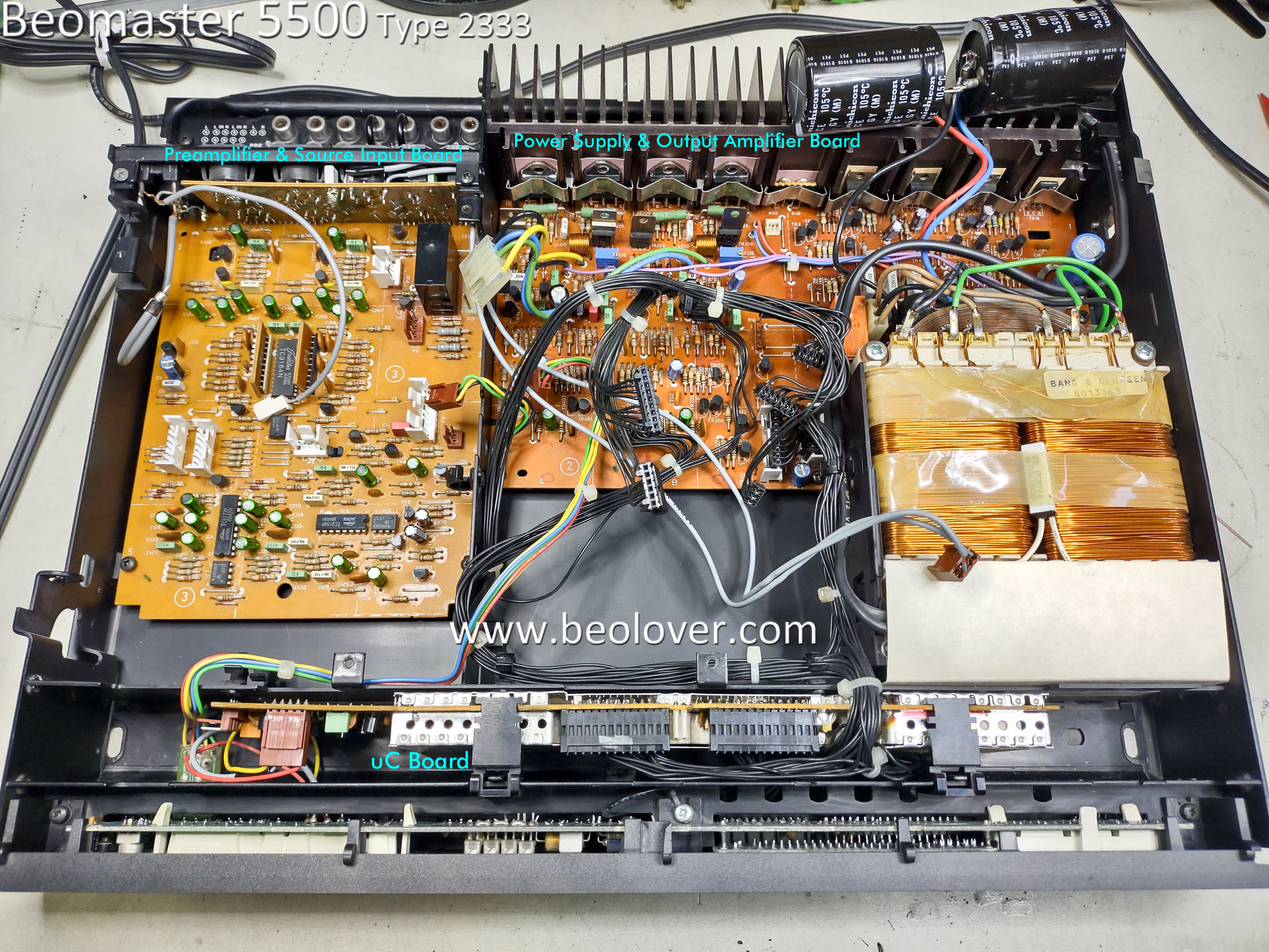
The first step was to remove the boards that will need to be worked on.
Here is a photo of the Beomaster 5500 prior to removing the boards.  The boards that will be worked on are labeled in the photo.


The following pictures are a sequence of Beomaster 5500 photos showing the boards being removed.


The last photo above shows the Microcomputer board removed...so I will start with that one.
Here are the before and after pictures of the Microcomputer board restoration.
There are just two electrolytic capacitors in this board.
There is also a CR2430, 3V Lithium battery.  It still measured 3V but it is still good to go ahead and replace the battery with a brand new one.


Note that for installing the new CR2430 battery I installed a battery holder for it.


The next board assembly is the Cooling Fan assembly.  It also has two electrolytic capacitors that I replaced.


The FM board came next.

Here is the FM board as it was received.


Here is the FM board after the electrolytic capacitors were replaced.


Here is the recapped Preamplifier board.  I didn't take a stand-alone before recapping photo of it so here are a couple of after recapping photos.  I replaced all of the signal path electrolytic capacitors with non-polarized, Nichicon audio capacitors.

Note that the highlighted Muting Relay had already been replaced so I didn't change that component.


The last Beomaster 5500 circuit board I worked on is the Power Supply and Output Amplifier board.
Here it is removed from the cabinet prior to any restoration work.


The white thermal compound on the heatsink assembly is just getting to the point where it feels a little bit dry.  For that reason I decided to remove the heatsink, clean the old thermal paste off and put new thermal protection on during re-assembly.

Here are photos of the heatsink removal and thermal paste cleanup.


Here is the Power Supply and Output Amplifier after I replaced the electrolytic capacitors, power supply relay and trimmer resistors for the output transistor bias.
There are two signal path blocking capacitors (2.2uF) for the audio signal from the Preamplifier board to this board.  I replaced those two capacitors with the same type I used in the signal path on the Preamplifier board.


Here is a closer photo of the new trimmer resistors.


The original power supply relay looked like this, de-soldered from the board.


The relay (RL1) still works but judging by the heat marks on the board and the fact that the Muting Relay (same type of relay) was already replaced...it is a good idea to go ahead and replace this relay.

I used a modern, enclosed relay.  It has two extra relay contacts that I had to cut off so that I end up with an identical mounting foot print.  I have used this replacement relay before on my own Beomaster 5500 and Beomaster 5000 amplifiers so I know it works well.


The next steps are to re-install the output amplifier board heatsink assembly then re-install the boards back into the Beomaster 5500 cabinet.

Friday, September 8, 2023

Beomaster 5500 Type 2333: New Beomaster Restoration Project From St. Louis

Most of my Bang & Olufsen restoration projects are on analog components from the seventies and early eighties.  However, I do own fully restored Beosystem 5000 and 5500 components which are from the mid to late eighties.  Those systems always include a CD player of course and continued the fully integrated system remote control that B&O started in the early eighties.

This project is a restoration of a Beomaster 5500 from an original owner.
It is an analog audio component that has a digital control system for operating it (Master Control Panel MCP5500).  

Here is the initial assessment of its condition.


It is a little dusty but that isn't a problem as I will be cleaning it as I do the restoration work.

The shiny aluminum top trim piece is pretty marked up.  That is due to the other Beosystem 5500 components stacked on top.  B&O designed these components to be stacked so it isn't a surprise to see the tops showing signs of wear like this.

The Beoparts store sells replacement aluminum trim to restore the cabinet if someone wants to make it new looking again :-).

Here is the back view of the cabinet.


A feature that I really love about the B&O cabinet design on these is how easy it is to open it up for servicing.

Two screws are loosened (not removed...and lost).  That allows two locking brackets to be raised up and held in place by tightening the screws again.


The unlocked cabinet top then slides back a little and lifted off.

Here is the Beomaster 5500 with the cabinet top removed.


The five highlighted screws are removed next to allow the AM/FM Stereo Tuner board to lift up into service position.

Some of the screws were loose so I suspected this Beomaster had been in for some service at some point in its history.


Flipping the unit around I could see that the audio muting relay has been replaced already.
That is a component I would have replaced if it was still original.


The same type of relay was used for the power supply rail voltages.  They get disconnected when the Beomaster 5500 is in Standby mode.

That relay is still original so I will be replacing that one.

Next, I removed the translucent, plastic air duct the helps cool the output amplifier components.


Everything looks good so far. 

Now to see if the Beomaster 5500 can be turned on and switch through its operation modes.

To do that I will use my own MCP5500 (Master Control Panel).
Unlike the Beomaster 5000, the Beomaster 5500 does not have a control panel built into it.
There are a couple of push buttons on either side of the front panel to turn the Beomaster on and off...plus some really minimal source switching.  You have to use the MCP to really operate this receiver.

Plugging the Beomaster 5500 in, it goes into Standby mode, which is what it is supposed to do.


I exercised the operation of the Beomaster with the MCP and could hear the relays engage when I went out of Standby mode.


It appears that all of the selectable functions work so I am ready to move forward and start the restoration.

From what I have seen so far I will replace all of the old electrolytic capacitors with new capacitors.
I will replace the power on relay.
I will also re-flow solder joints on the boards.  That will guard against any unseen breaks in the electrical paths.
The Beomaster has a small, lithium battery for its built in memory to remember user settings.
I will replace that battery.
The thermal compound on the output amplifier heatsink looks like it is still soft (not dried out).
So I probably will leave that as it is unless I see the amplifier getting too hot during testing.

This Beomaster 5500 cabinet is missing its rubber cabinet feet.  That is pretty common and expected.
I will replace those feet with a set that Beoparts reproduces.  Typically all of the audio components in these B&O systems (5000, 5500, 6500, 7000) have missing or broken cabinet feet.

Once I get the restoration work complete on this receiver I will be able to test it using my various Beosystem 5500 components and the MCP5500.