That post left off with the output amplifier heatsinks needing to be re-installed on the Power Supply & Output Amplifier board.
I used Sil-Pad thermal insulators in place of thermal paste as it is easier to work with (less messy) and does a great job. There are two lone transistors (IC205 and IC405) that fit between the heatsink channels that do require some thermal paste compound as they don't have spring clips to press them against the heatsink (like the other, larger transistors do).
I used Sil-Pad thermal insulators in place of thermal paste as it is easier to work with (less messy) and does a great job. There are two lone transistors (IC205 and IC405) that fit between the heatsink channels that do require some thermal paste compound as they don't have spring clips to press them against the heatsink (like the other, larger transistors do).


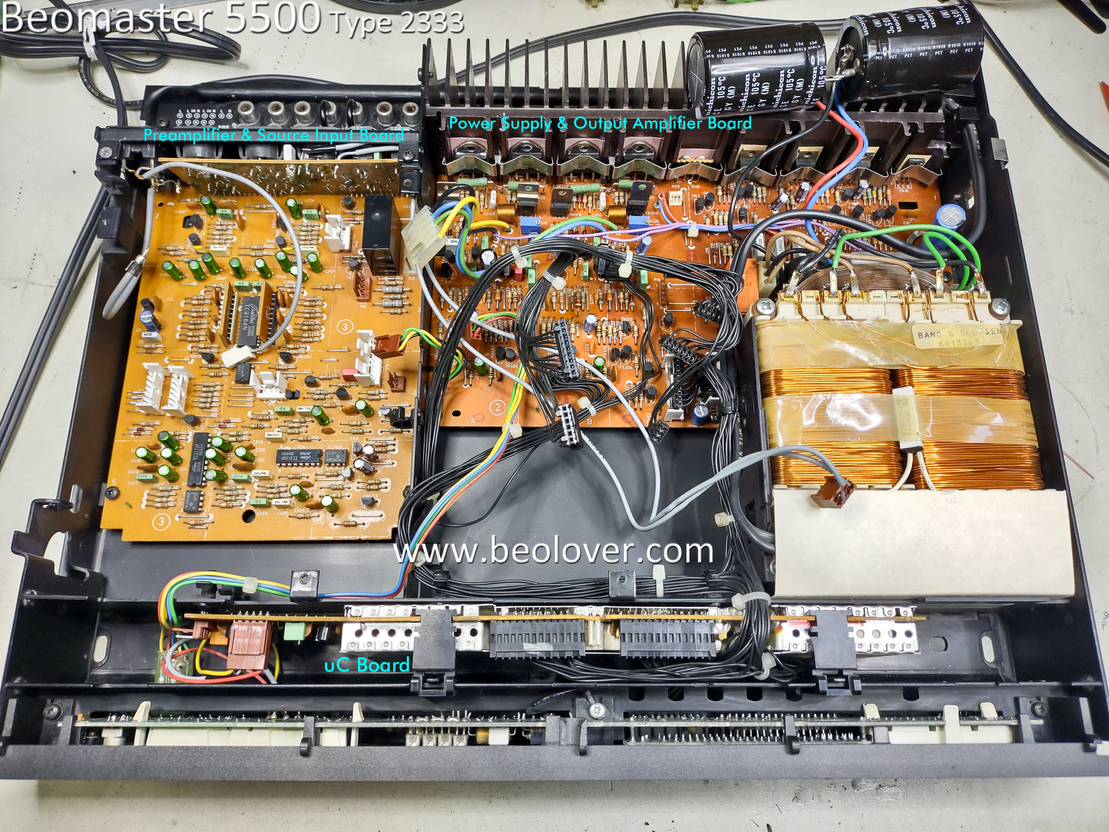
The next set of pictures show the re-assembly of the restored boards back into the Beomaster 5500 cabinet.


With the circuit boards re-installed I was able to plug the Beomaster 5500 into AC power and do some initial tests on the Beomaster.
I did some quick measurements of key DC voltages with the Beomaster turned on.
The positive and negative 40 volt rail voltages were there as well as 5 volts, 8 volts, 12 volts, 13 volts and 28 volts.
I adjusted the Left and Right channel no-load current biasing for the Output Amplifiers and then tried playing some music with the Beomaster.
Here are photos of my measurement probes for the the no-load current adjustments.
That adjustment requires the Beomaster 5500 to be on (out of Standby), have the volume level of the amplifier set to zero and no speakers connected to the amplifier.

The trimmers were adjusted so the voltage reading across the emitter resistors of the channel measured 11 millivolts DC.
The Beomaster 5500 was now ready for a quick listening test.
When the voltages check out and the no-load (idle) current has been adjusted, I like to do a listening check of the amplifier. It is like an early reward for the restoration work to get to this point.
I connected up two sets of Beovox speakers in the workshop. A pair of MC120.2 speakers and a pair of S-55 speakers. For a music audio source I connected an iPod to the Beomaster 5500 CD source input.


The Beomaster 5500 sounds great (as expected).
Now I can complete the rest of the Beomaster 5500 reassembly and move on to some audio tests.
I will also be doing some functional testing of this Beomaster 5500 with other Beosystem 5500 components and the MCP remote control.
No comments:
Post a Comment
Comments and suggestions are welcome!