Featured Post

Beogram Commander Remote Control: Maybe This is the Final Version!..;-)

This is a follow up to my recent post about the redesigned Beogram Commander remote control board, which now works in both (DC-motor) Beogr...

Saturday, October 31, 2015

Beomaster 8000: Repair of a Ripped Off Keypad Ribbon Cable

I recently repaired a ripped off ribbon cable in a Beomaster 8000 that connects the volume rotary encoder to the microcontroller board. I thought I was done, but the front panel came back, now with the frequency encoder cable broken off. The hot glue that I used to fix it in place had come off from the cable, and subsequently it broke off during the rigors my customer's restoration effort put on the solder points:

At least this time I was able to reuse the cable in its full length, so I could simply remove a bit more insulation and solder it back in. I removed the keypad PCB, cleaned the solder points and then did the soldering:
Then I glued it on with epoxy to the PCB back, hoping this will be more durable:

After that I reattached the PCB using new (they should not be reused after taking them out) 3mm retaining clips and nylon washers to protect the PCB. Then it was time for testing. I put the panel into the Beomaster 8000 that I am currently restoring for another customer and turned it on. I tested all keypad buttons and both encoders, and everything seemed to work properly. I hope this was the last time I worked on this particular panel and this 8000 will finally be happy!

Beomaster 8000: Volume Encoder Damping Restoration - The Final Answer

The Beomaster 8000 that is currently on my bench had lost all damping of the volume rotary encoder wheel. This issue is more than a cosmetic one, since damage can occur to the speakers if they are not dimensioned properly if someone accidentally spins the volume encoder up to 6.0. Without damping this can easily happen if attention is not being paid. Up to now I used a method to restore the damping that was based on a 3D printed paddlewheel that I clamped on the back of the encoder shaft and then filled the cavity with a high viscosity damping grease. While this worked fairly well, I always had the feeling I was on the wrong track with this. So yesterday, I finally took the plunge and opened up the volume encoder to have a look under the hood with the goal to understand how the original damping had been done. After taking out the encoder sensor assembly I cut the retaining clips off with a wire cutter (unfortunately this seems to be the only way to get them off) and removed the encoder:

It is held by four adhesive strips and I needed to use a screwdriver to lift it up one corner at a time. Once I had it out I thought what a beautiful big design compared to today's encoders...Anyway, once the encoder is off, one can simply pull out the wheel from its precision sleeve bearing:

And after I saw this everything was clear: The original damping was simply done by putting some damping grease on the shaft and then inserting it back into the bearing. Due to the fairly tight fit this creates a nice damping effect. Unfortunately, over time this grease is entropically driven out of the bearing, and the damping effect wanes gradually. I put some Nyogel 767A on the shaft

And inserted the wheel into its bearing and the wheel was damped again. I put the encoder assembly back onto its posts and clamped it down with new 3mm retaining clips and nylon washers to protect the encoder housing in case it needs to be opened up again in another 20 years for a re-greasing:

Then I adjusted the plexiglass clamp in the back to ensure scraping free operation while being flush with the surface of the Beomaster keypad. I guess the evolution of my fix to this issue is another example of live-and-learn. I should have taken one apart much earlier...;-).


Thursday, October 29, 2015

Beogram 4002 (5513): Sudden RPM Changes

I thought I was pretty much done with the Beogram 4002 (5513) that I recently restored and I started testing it by listening to my favorite vinyls. After a while I realized that the RPM drifted over time. This was cured by replacing the original RPM relay with a drop-in replacement based on a modern encapsulated signal relay and exchanging the original principal 5k RPM trimmers on the circuit board with modern encapsulated multi-turn precision trimmers. Here are a few impressions:
This shows the original RPM relay on the main PCB:
This relay is the same as used in the Beogram 4000, so my recent design of a replacement of the 4000 relay could be fitted here, too. This shows the drop-in replacement board:

And installed:
Above-left of the relay are the original 5k trimmers. I replaced them with these:


The lead-extensions were needed since I had to install them upside down to make sure that the set screws are accessible through the PCB from the solder side. Otherwise, it would be impossible to tune the RPM while the deck is running:
Here is a top-view:

This solved the RPM drift issue. However after a lot of listening to vinyls, most notably an original first pressing of a 12" single of Grace Jones' "Slave to the Rhythm", it became apparent that in addition to the drift phenomenon there was an other, more serious issue: Sudden sharp drops in RPM that would only occur on relatively rare but completely random occasions. Not so great! I decided to get to the bottom of this and I connect my oscilloscope to the signals around IC3 that controls the DC motor feedback control loop. To observe these signals while a record is playing one needs to solder jumper wires to the interesting signals of IC3:
This enabled to hook up my 4 channel oscilloscope:

Here are the traces that I measured during the occurrence of the phenomenon. Luckily once the issue started to happen it reoccurred a few times in a row, allowing me to capture traces with the single shot button. This shows the phenomenon at 33 RPM

and the much more frequently occurring analog at 45 RPM:

The traces are assigned as follows (see circuit diagram below): blue pin 1 (this is the AC induction signal from the DC motor feedback coils), yellow: pin 6 (this is the pulse width modulated output from the Schmitt trigger that corresponds to the amount of power the motor receives, green pin 7 (this is the RC network that determines the actual pulse width that the Schmitt trigger puts out, and red pin 4 (this voltage relative to the TR2 stabilized 8.5V output corresponds to the voltage the motor receives).
All this was pretty interesting: The DC motor of the Beogram 4002 (5513) is a 3-pole motor. This means that each of the three coils on the rotor is fully powered up every six commutator contact changes (see here for some awesome animations and basic info). This suggests that the observed aberration in the pin 1 traces are related to one specific cycle of the motor rotation since the 'missing valley' phenomenon occurs every 6 wave cycles. So I took the motor apart again and throughly cleaned the commutator and the brushes and put it back together. This made the phenomenon much rarer but did not alleviate the issue completely. I may go ahead and put the motor of a parts unit in for now until I figure out how to fully fix this. The issue with intermittent problems is that they are intermittent. So it is difficult to make sure that a fix 'sticks'  100%. All this shows the principal issue with DC motors in turntables: They need a precisely working feedback mechanism to keep the RPM constant. All this is a non-issue with AC synchronous motors that simply 'obey' a sine wave that is fed into them. 


Wednesday, October 28, 2015

Beomaster 8000: Display Restoration with SMD LEDs

After I replaced the indicator light bulbs of the Beomaster 8000 that I am restoring right now I did the 7-segment displays. The 7-segment displays are essential for the signature looks of the 8000 and dead segments are at best annoying. I usually recommend to rebuild the displays even if they are still o.k. since the death of individual segments is virtually unavoidable considering the age of the units and the potential rigors of shipping. The original LEDs in these displays are not encapsulated, i.e. the bonded contact wires are not protected against vibration and thermal challenges etc.... Therefore, the usual failure mode is loss of contact at the bonding locations. Final failure is often preceded by intermittence as these wire bonds. This Beomaster had a few segments in this stage, which may or may not explain the claim by the seller that the displays were in good working condition. I posted many entries in the past about my restoration process, a summary can be found on my dedicated Beomaster 8000 page. The pictures shown here are posted to document the work done on this particular Beomaster 8000.

This shows the display board after I extracted it:

This shows the displays after unsoldering them. It is mandatory to use a desolder gun for removing them to prevent damage to the fragile pre-FR4 age PCB:

Then I liberated the displays from their plastic mounts,

and opened them up:
Then I removed the original LEDs and then soldered SMD LEDs into place. Then it was time for my 24hrs test where I power the boards from a test-jig that I set up with a couple solders breadboards:

Then I put the covers back on and tested them again to make sure all segments survived the procedure:

Then it was time to solder the displays back in. Here you can see them mounted back on their plastic mounts:

And back on the PCB: 
And fired up together with the newly rebuilt indicator lights (unfortunately I forgot to use a FM preset, so the source display is dark in this picture). The volume is a 6.0 to get the clipping indicator to light up:

On to the uProcessor board.


Beomaster 8000: Replacing the Incandescent Indicator Light Bulbs with SMD LEDs

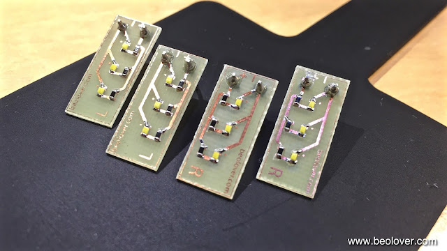
I always enjoy rebuilding the display board of Beomaster 8000s. So much of the signature looks of these units depends on the gorgeous large 7-segment displays and the masked indicator lights for clipping, filters, mono and manual tuning. With this particular unit I started out by replacing the indicator bulbs with my recently designed SMD LED based replacement boards. There are two versions of this board accommodating the two left and right incandescent bulb cabinets. The contact pads for the bulbs are mirrored in these compartments, while the polarity remains the same. This mirror symmetry requires different boards to accommodate polar devices like LEDs. Here is a picture of the boards that I installed:

When I developed these boards I made a video how to install them:

It is important to keep in mind that the LED boards run on a much smaller current than the light bulbs, and this requires the removal of the resistors R34/36/38 and 40 on the display board. Otherwise the LEDs will always be on.

This shows the original light bulbs in their cabinets:

And after replacement with the SMD LED boards:

And in on condition:

On to rebuilding the 7-segment displays.


Monday, October 26, 2015

Beomaster 8000: Recapping the Tuner Boards

The final boards to be recapped in the Beomaster 8000 that I am currently restoring were the FM tuner boards. Here are some impressions of this effort. This shows the boards with the original capacitors:

And here after replacing all electrolytic capacitors with 105C grade Japanese units:

With these boards it is especially important to clean the contacts between the boards and coat them with DeoxIT. I had several cases in the past where one channel did not work on the tuner, which could directly be traced to a contact issue between these two boards. After I put everything back together I tested the Beomaster and everything works fine now!
This concludes the recapping of this Beomaster. On to the displays and the uProcessor boards. On into the heart of the dragon...;-)


Sunday, October 25, 2015

Beomaster 8000: New Electrolytic Capacitors for the Control Panel and the Preamplifier

I made some progress with the recap of the Beomaster 8000 that I am working on right now. Today I did the control panel and the preamplifier boards. The control panel pcb is bolted to the control panel fixture, and one needs to unsolder the leads to the signal strength meter. After that is done the PCB can be extracted:

Here is a shot of the board after replacing all electrolytic capacitors with 105C grade Japanese units:

As usual, I also reflowed all solder points on the wire-to-board connectors and coated the pins with DeoxIT D100 for longterm stability.
After I put the control panel back together I moved on to the preamplifier board. It seems one 10uF capacitor had already been exchanged at some point. These red electrolytic cans are often problematic at this age.

I replaced all of them with new ones and also did all the connectors:

Here a detail shot:

On to the tuner boards, which will conclude the recap of this Beomaster 8000!


Thursday, October 22, 2015

Beomaster 8000: Rebuilding the Power Supply Board

After replacing the original main reservoir capacitors of the Beomaster 8000 that I am restoring right now it was time to do the remaining power supply. The golden reservoir capacitors often fail at this age. Another often found dead capacitor is the 5V rail cap, since it is directly mounted on the 5V regulator (on the heat sink on the right side of the Beomaster enclosure), and therefore sees elevated temperatures. Here is a photo of the original power supply board:

and after replacing all the electrolytic capacitors with quality 105C grade Japanese units:

Before putting the assembly back into the Beomaster I also cleaned and reflowed all headers, and coated the pins with DeoxIT D100 for lasting oxidation protection. On to rebuilding the remaining boards...

Tuesday, October 20, 2015

Beomaster 8000: Replacing the Speaker Switches with Modern Encapsulated Units and Laser Cut Adapter Plates

After my second round of output PCB troubles in the Beomaster 8000 that I am restoring right now, I put in new speaker switches. The heatsink cover was still off, so this was a 'good moment'. I implemented modern encapsulated switches and laser cut adapter plates that make them fit into the original bays for the switches. A while ago I made a short video about this process, that also shows the laser cutter in action...what's not to like about digital manufacturing methods!:


These pictures document the procedure on the particular Beomaster 8000 that I am rebuilding. This shows the original switches in place:

Here they are 'folded' out and the original mounting plates are visible:

This shows the original switches in comparison with the new replacements and their adapter plates. Note that the here used most recent design iteration has laser etched tabs on the narrow sides of the plates since I was not able to find plexiglass sheets of the same thickness as the original base plates of the switches:

These switches and adapter plates are available to other enthusiasts, just send me a message.

Here they are soldered in place:
This picture shows them held in place in their bays. The laser cut plates exactly fit in the cutouts and the precisely laser etched thickness of the tabs ensures that the switches are at the right height when the heatsink cover is installed:


Monday, October 19, 2015

Beogram 4002 (5513): Installation of the Latest Version of the Beogram Commander Remote Control

On occasion of my latest Beogram 4002 (5513) restoration, I updated the Beogram 4002 Commander remote control that I developed earlier this year with a 'pairing' function, that eliminates potential conflicts between the Commander's Apple remote and pre-existing Apple TVs etc... I also added the ability to switch between 33 and 45 RPM remotely, thereby fully eliminating the need to use the keypad ever again (to protect it's fragile lacquer coating from skin acids etc...). I made a video about the latest version that explains the functions in detail, and also gives a demonstration of the remote functions as well as the pairing mechanism:


Here are a few impressions of the Commander board as it was installed in the Beogram 4002. This shows the Commander board including its 3D printed tray and mounting 'plug'. The board plugs directly into the keypad connector on the main PCB of the Beogram. The mounting plug enables reusing of the original PCB mounting screw that is located beneath the board to safely fix the Commander board into place once it is plugged in:

This shows the board installed. The keyboard connector is plugged into the white on-board connector and routed through to the original connector on the main PCB. This ensures continued functionality of the keyboard with the Commander installed.


Sunday, October 18, 2015

Beomaster 8000: More Output Trouble - Broken TR207 Collector Trace

After I fixed the broken PTC thermistor lead in the left output of the Beomaster 8000 that I am restoring right now, I thought I was finally done with the outputs, but no: When I tested it for a while it ran happily, and then out of a sudden the fault switch triggered again a shutdown of the output supply. This one was difficult to find since it turned out to be intermittent. After a while I finally figured out that the trace that connects the collector of TR207 (voltage gain stage) to the positive 55V rail was cracked. After removing the delaminated trace, I fixed it with magnet wire:

I like to use magnet wire for fixing traces, since the polyurethane insulation of the wire can conveniently be burned off with the soldering iron, resulting in short circuit proof connections that are insulated right up to the solder point.
Unfortunately, this did not fully fix the output issue. While the 8000 came on again reliably, I realized that my repair efforts must have caused some other problems. More trouble shooting finally yielded another broken off lead to the heat sink. It must have broken off while I lifted the board up to do fix the trace. The many alterations on this board and also the left channel suggest that the previous owner had a hard time to pinpoint the issue with the intermittent trace and the fault switch issue, and therefore the board was lifted a few times too many for replacing components finally compromising the integrity of the leads that go to the heatsink. This time the (green) lead to the base of IC205 broke at the solder terminal on the PCB. This caused this Darlington to be turned off. It was remarkable that the output still amplified under this condition. I only noticed the issue since after repairing the trace I ran the output with external power supplies while measuring the voltage drop across the R236/7 emitter resistors, which could not be raised anymore above 3 mV. This indicated that there was something wrong. After I reconnected the base of IC205 everything was finally good again. Live and learn. No Beolove without some degree of pain, I guess...;-)


Thursday, October 15, 2015

Beomaster 8000: Replacing the Output Reservoir Capacitors

SinceI had the Beomaster 8000 heat sink cover off while working on the output stages it was a good moment to also replace the original 10000uF reservoir capacitors. I always enjoy replacing these with modern units and my custom designed 3D printed adapters to make them fit snugly into the original bays. Here are a few pictures:

Here is a shot of the replacement units with their 3D printed adapters (these adapters are available to other enthusiasts - just send me an email). I currently use quality Japanese 105C caps from United Chemi-Con (EKMH630VSN103MA50M):


This shows the original capacitors of the left channel:

And after installation of the replacements:

Here is the original right channel:

And the replacements installed. I had to put on shrink tubing (yellow in the photo) onto the original leads to make them short circuit proof. Some amateur overheated the insulation while messing with something back there and it was a bit frayed at the ends.

On to the speaker switches!