Featured Post

Beolover SyncDrive: DC Platter Motor Replacement for Beogram 4002 and 4004 (Type 551x and 552x)

Late Beogram 4002 and the 4004 (Types 551x and 552x), which have DC platter motors instead of the earlier synchronous AC motors usually suff...

Monday, March 30, 2020

Beomaster 4400 Type 2419: Changing out the power on/off switch

From the work so far on this Beomaster 4400 I know there is a power on/off switch problem. Specifically, the switch will not switch the Beomaster off. In the previous post I prepared a replacement switch from a spare parts Beomaster 4400 unit. In this post I will open up front panel of this project's Beomaster and swap out the power on/off switch.

Here is the power on/off switch again as found in the Beomaster.


That is as far as you can go without starting to disassembly the Beomaster 4400 frame/chassis components again. You can see that the other side of the switch assembly is blocked by the large circuit board of the Beomaster.

I definitely don't want to disturb the main PCB and the transistors on the heatsinks again just to change out the power on/off switch.  You can loosen the front part of the Beomaster 4400 frame and extend it forward to get to the switch assembly and eventually the power on/off switch.

The other side of the Beomaster shows what I am talking about regarding access to the switch.
I have outlined the power on/off switch and Power On lamp for reference.


I had taken the front panel of the Beomaster 4400 earlier when doing the capacitor replacement but I didn't go into the front panel itself other than remove the slider controls for cleaning.

This time I need to be able to pull the front panel far enough away from the rest of the Beomaster so I can access the power on/off switch.

Starting with the front panel itself, I had to disassemble the front panel from the left and right Beomaster side rails.  There are two screws for each side.


After that I am able to start pulling the front panel forward but it still has a long way to go. There are some wires that limit the travel as well as the front panel screws that attach to the transformer and reservoir capacitor brackets.


This picture shows the front panel pulled away slightly but still restricted.


I decided to desolder and get the solid blue and striped blue/white wires out of the way next.


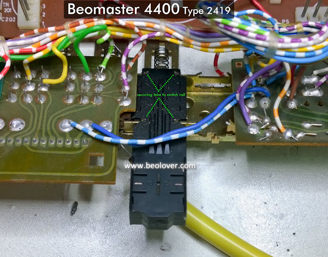
Now the power on/off switch mounts can be seen.


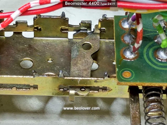
There are four mounting tabs holding the switch to the switch rail assembly. The tabs are small and must be carefully bent to free the switch for removal. I still felt I didn't have enough operating room to remove the switch.

I really needed to pull off the front panel to access everything I needed to get to.

I removed the three screws that mount the switching rail assembly to the front panel.


I removed the headphone jack assembly


I removed the screws from the brackets for the FM Strength Meter, FM Tuning Dial and the FM Presets.


That left the FM Stereo LED still in the front panel. I didn't want to risk damaging the LED assembly by trying to remove it so I desoldered its two connections and pulled the wires out of the small bundle they were in.


Now the front panel is removed and I can get down to business with the power on/off switch.

First I removed the metal pushbutton parts. Technically, the metal switch part of the assembly could be left intact but I wanted to go through everything.


The switch assembly can finally be removed from the switching rail assembly.


Opening up the switch assembly reveals how burned up the switch contacts were.


These switch components look pretty bad. No wonder the switch wasn't working.
Fortunately I don't have to attempt to get them into some sort of working order and risk future problems. These power on/off switch assemblies are a real ordeal to access so I want a good replacement switch.

Fortunately I have the spare power on/off switch from the parts unit. The contacts and actuators have all been cleaned, polished and ready for reassembly.

After placing the components back in place I sealed the seam of the switch assembly with some black hot glue. It will help secure the switch assembly and can be peeled off in the future if it is ever necessary to open the switch again.


Now to install the power on/off switch back on the switching rail. Here is a sequence of photos showing the reinstallation of the power on/off switch.


There we are. A working power on/off switch again. Now for the task of reassembling the Beomaster 4400 front panel again.

Sunday, March 29, 2020

Beomaster 4400 Type 2419: Investigating the Power On Problem

I left off this Beomaster 4400 restoration thread having reassembled the receiver for a power on test.
That did not go as I planned and it appeared there was a problem with the right channel output amplifier circuit.

I disassembled the Beomaster 4400 partially so I could de-solder the leads to the output amplifier transistors that mount on the heatsinks.  I found two bad right channel TIP 146 Darlington transistors. That being the case I ended up checking all of the output amplifier transistors for both the left and right channels.

For reference, here are the locations and transistor types.


After replacing the two bad TIP 146 Darlingtons I was ready to try the power on test again.
The dim bulb remained off, so a good sign there, and I reached the line voltage level of 125 VAC, 60 Hz on the variac.

The +15 VDC power supply measured good as did the ±35 VDC rail voltages. Before I could continue with the other power supply measurements I noticed my voltmeters were starting to show the rail voltages going down.  They were decreasing slowly (increments of about 50mV) but they were dropping. The ammeter on the variac wasn't showing much of a current draw but something was wrong...so off with the power again and abandonment of another power on attempt.

During the power on test I noticed that the Beomaster 4400 power on lamp was not illuminating.
Before trying another test I pulled the lamp and checked it.  It was indeed burned out so I replaced it.

Here is the location of the lamp and the replacement.


With a replaced Power On lamp the Beomaster 4400 now indicates power is applied.

While that was good you can see a new problem...The Power On lamp remains on all of the time, even when the Beomaster is switched to the Off position.


Definitely a sign that there is a problem with this Beomaster 4400 On/Off switch.

So far I had only been leaving the Beomaster powered on for a few seconds.  I wanted to collect some more information regarding the Beomaster losing power.  I connected my DMM measurement tools to the transformer secondary and rectifier outputs for ±35 VDC.  When I applied power with the variac I ended up with a reading of over 52 VAC across that secondary.  Sure enough, it started to drop.
I had planned to monitor the voltage drop for a while but began to notice a wisp of smoke coming from the Beomaster 4400 Power On/Off button...power down time again.

Now things are starting to add up.
In the power supply circuit diagram here -


you can see that the Beomaster 4400 applies line voltage to the receiver power supplies entirely through the On/Off switch.

Note that this is a Type 2419 BM4400 and has a fixed line voltage for the USA.

After years of powering on and off the switch contacts start to wear and get pitted. This Beomaster's On/Off switch must have welded closed from all of the arcing during power on cycles.

Of course I will need to verify this but now I know I have to go through the steps of replacing the Power On/Off switch.

Here is the Beomaster 4400 On/Off switch.

That switch assembly will have to be removed and most likely replaced with a spare.

First however, I will remove the replacement switch from the spare Beomaster 4400 and check that On/Off switch to make sure it is in good working order.  It is a lot of work to remove these switches so I want to make sure I am replacing the bad switch with a good one.

Here is the Power On/Off Switch removal and disassembly.


These pictures show the switch on and off actuation.


You can see in the photos that there is a lot of debris from arcing that occurs when the Beomaster was turned on and off.  All of this will be cleaned along with the switch contacts.

Speaking of which....Here are the actuators removed. The pitted contact points are easily seen.


I sanded both the actuators and the four fixed contacts as part of the switch cleanup.


Now for the ordeal of removing the Power On/Off switch of the Beomaster 4400 I am restoring.