Featured Post

Beolover SyncDrive: DC Platter Motor Replacement for Beogram 4002 and 4004 (Type 551x and 552x)

Late Beogram 4002 and the 4004 (Types 551x and 552x), which have DC platter motors instead of the earlier synchronous AC motors usually suff...

Showing posts with label voltage checks. Show all posts

Tuesday, August 11, 2026

Beogram 4004 Type 5526 - Restoration Project - SyncDrive and Remote Commander Installation

Continuing on from this project's previous post, I needed to install a Beolover SyncDrive platter motor and a Beo4 Remote Commander.

However, there were still some other follow-up tasks like checking the 21V supply voltage (to make sure it doesn't have any noise), adjusting the TR3 collector voltage with the new R26 trimmer, installing a Beolover platter detector lamp replacement, installing Beolover RPM indicator LEDs and running the platter speed calibration.

Here is the 21V measurement check.  The inset oscilloscope screenshot is zoomed in on the 21 V line so I could check the ripple. The measurement looks very good.


Next, I installed a Beolover platter detector lamp module so I could check (and adjust) the platter detection signal with the 1TR6 trimmer I installed (in an earlier post).
Once the 1TR6 trimmer was properly set, I moved it over to the component side of PCB1.


I changed the speed indicator lamps in the Beogram 4004 RPM indicator panel to Beolover LED modules.


Now I could install the SyncDrive platter motor, run its speed calibration and test the platter detection functionality of this Beogram 4004.


SyncDrive speed calibration...


At this point I was able to calibrate the Beogram 4004 record tracking.

I removed the platter belt for this calibration procedure so I could rotate the platter by hand and check the Beogram 4004 servo motor performance when advancing the tonearm.


While this procedure is usually a repetitive adjustment and measure series of steps, I was pleasantly surprised that I was able to lock in the correct setting only using the coarse screw adjustment shown in the picture above.

Usually I get the setting close using the coarse adjustment, then dial in the final setting with the Beogram 4004 eccentric screw adjustment and/or the Beolover tracking lamp trimmer.


Now for a quick check of the platter detection signal and the position sensor run-out groove detection.

The empty platter detector signal looks good.


Previously I had adjusted the position sensor to output 5V when the clear part of the position scale was in front of the detector.  Note that when the blacked out part of the scale is blocking the sensor, the voltage is around 10 V.  Those can be checked and adjusted (using PCB1 trimmer 1R88) without the platter motor if desired.


The last section of the position scale has a series of narrow black bars.  This is so the position sensor will generate a series of pulses that the detection circuit on PCB1 can interpret as the run-out groove of a record. Each run-out pulse adds to the voltage level that capacitor 1C33 charges up to in the detection circuit until the detection threshold is reached. At that point, the run-out detection circuit initiates a stop and return to end the record play.

This picture shows the position scale bars entering the position sensor area. The inset oscilloscope screenshot shows what the run-out sensor signal looks like when the tonearm is moving through the run-out groove.  In this case the run-out detection circuit triggered on the third pulse.
Note: My measurement point here was at the node for 1D41, 1D42, 1C33 and 1R82 on PCB1.


Last, but not least, was to install the Remote Commander...but first, I still had to clean the old oxidation off the Beogram 4004 control panel button contacts.  I applied some Deoxit fluid on the cleaned contacts.


While checking the button panel I discovered that one of the buttons was badly damaged and would not work.  I replaced the plastic button with a spare.


With the button panel restored and tested, I install the Beolover Remote Commander.
This version of the Remote Commander is designed to operate using a Bang & Olufsen Beo4 remote control.

Also...note that the Remote Commander installation is using the Beogram 4004 options.


Using the Beolover Remote Commander with a Bang & Olufsen Beo4 remote control can be a little bit tricky.  That is because the Beo4 remote control is configurable and may not be ready to work with controlling a Beogram right out of the box.

This was the case I ran into with this Beo4.  It did not have the Phono option in its list of supported components.  Adding that to the Beo4 menu list is not difficult but it wasn't intuitively obvious.
Beolover describes the setup in this video.

This Beo4 had one additional wrinkle however.  It did not have a Phono named function in its memory to add to the list of components.  It did have "N. Radio" which, it turns out, is another function name that works as a phono selection.


My next step will be to reassemble the rest of this Beogram 4004 and do some record play testing.

Wednesday, November 16, 2022

Beogram 8000 Type 5613: Wisconsin project is ready for record play

I finished the service manual checks and adjustments on this Beogram 8000 turntable.
The power supply voltages look good. The forward/reverse scanning LDR adjustments are set.
Tracking force is calibrated as well as the record tracking sensitivity.

A quick workshop test play of a record shows that the Beogram is ready for some record play listening tests so I will install the components back into the Beogram cabinet and enjoy some records.

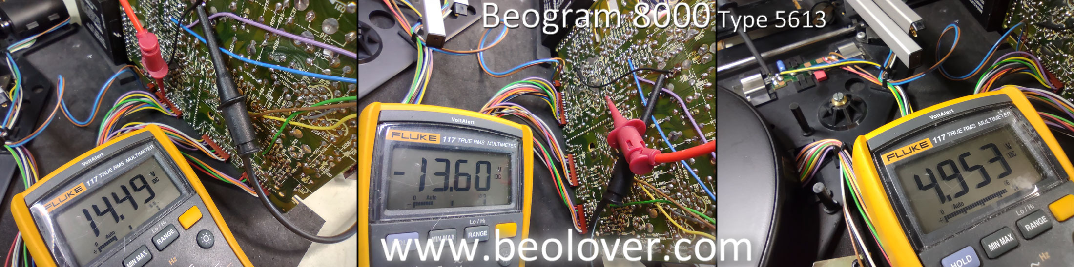
Here are the supply voltage checks at the filter capacitors and at the output of the regulators.
From left to right are +15 VDC, -15 VDC and +5 VDC.


In this photo I show using my little three pin test connector for adjusting the forward and reverse scanning sensors (LDR devices).  I like to set the idle voltages for these around 650 mVdc.


Next was calibrating the tonearm tracking force at the 1.0 gram mark on the adjustment scale.
I adjusted the counterweight at the back of the tonearm until the 1.0 gram mark on the adjustment scale measured 1 gram on the scale.


The final adjustment is for the record tracking sensitivity.  This is the adjustment where the P4 connector is disconnected from PCB 1 so the platter doesn't turn.  

The procedure calls for manually turning the platter with a test record.  The stylus is dropped onto a track in the middle of the record and the tracking sensor sensitivity is adjusted so the tangential arm servo begins advancing the tonearm assembly between 1 or 2 revolutions of the platter.  After that the servo motor should advance the arm every revolution of the record.


After a few iterations of the adjustment screw the sensitivity was set.

Before putting the Beogram 8000 all back together in its cabinet I wanted to listen to a couple of records on it while it is in the workshop.  I connected it to my Workshop Beomaster 8000 and gave it a listen.  Using the Beomaster 8000 also tests the remote control functionality between the Beogram 8000 and the Beomaster 8000.


The MMC-20CL cartridge played beautifully on the Beogram.  My Beomaster 8000 is connected to a pair of Beovox S75 speakers and did their part in the record play enjoyment :-)

Note: I keep my Workshop Beomaster 8000 opened up all of the time. It is fully functional where I can use it to listen to music while I work but it is always available to perform board testing with and that is its main purpose in the shop.

Sunday, January 23, 2022

Beomaster 2000 Type 2801: Replacing Some Components and First Music Listening Test

I received most of the electronic components I needed to restore this Beomaster 2000 receiver.
Compared to the last few Beomaster receivers I have restored this one will have the least amount of capacitors replaced.  As I mentioned in the previous blog post ...for this unit I will leave in all of the red tantalum capacitors if a spot check shows them to be good...and it did.

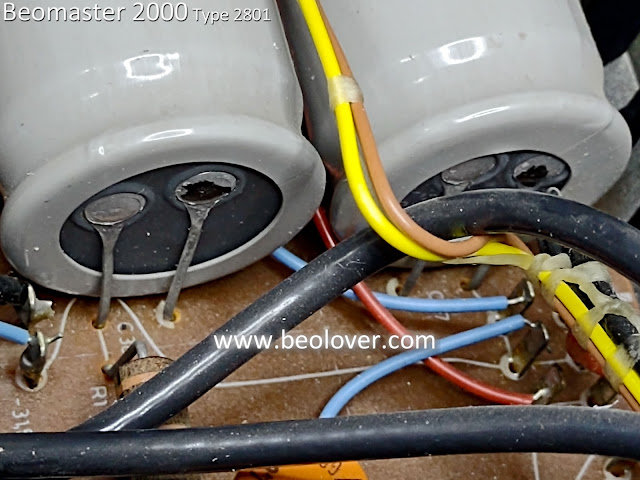
Here is a small sampling of three different tantalum capacitors from the Beomaster 2000.


I didn't remove and test every single tantalum but I tested enough where I was satisfied the plan to leave them in is sound (sorry for the unintended pun :-) ).

I did replace the electrolytic capacitors, the no-load current adjustment trimmers (two...one for the left channel and one for the right channel) and the 2D8 bridge rectifier.

Here is a before and after photo of the 470uF 2C24 capacitor and the 2D8 bridge rectifier (located on PCB 2).

Before:


After:


The output amplifier board (PCB 7) had seven electrolytic capacitors to replace and two 250Ω trimmer resistors for the left and right channel no-load current adjustment.

Before:


After:


Note: The thermal compound on the transistors mounted on the rear heat sink of the Beomaster 2000 cabinet was still soft so I left those alone.  If there ends up being a problem with the transistors and I have to replace any, I will rework all of the output transistors.
For now...they are left as they are.

PCB 5 (IF & Preamplifier) only has two electrolytic capacitors to replace.  Here are the before and after photos for that board.

Before:


After:


That sums up the PCB component replacement tasks.

PCB 3 (Pre-set Tuning board) required desoldering of the five pre-set dials.
The issue with this board was that the black, plastic adjustment knob for each preset was slipping.

I cleaned all of the preset components with some fader lube, glued on the plastic knobs and then reinstalled the five presets to PCB 3.


Next, it was time to check powering up the Beomaster and checking voltages.

I set the voltage selection switch to 130 VAC as here in the USA the line voltage is closer to 130 V than it is to 110 V (the other voltage switch selection option available to me).


On these initial power up tests I use my variac and dim bulb tester to protect any short circuits to ground in the Beomaster power supply path.

As you can see the line voltage is closer to 130 V than 110 V so 130 V is the best selection for my area.


For reference here is the Beomaster 2000 Type 2801 line voltage supply wire routing for the four voltage select options.  Top left is the wiring for my selection.


With the Beomaster turned on (Tape selected) I measured the secondaries off the transformer.
One set should be at 26 V and the other should be 46 V.


Those are good values for the power coming in.

Checking the resulting ±30 VDC rail voltages I measure -


Those measure good.

Now to check the +26 VDC adjustment called for in the Beomaster 2000 service manual.
I monitored the +26V test point and adjusted the trimmer to get as close to 26V as I could.


After that I adjusted the output amplifier no-load current for both channels per the service manual.
The adjustment calls for no speakers connected, the volume level at zero, the amplifier warmed up and a measurement of 10mVDC across emitter resistors (7R119 : LCh, 7R219 : RCh).

Here are those measurements using the new Bourns multi-turn trimmers I installed to adjust the voltages.

Left Channel


Right Channel


Those are all the initial voltage checks I wanted to do.
Now to hook up speakers and see if I have music playing from this receiver.

This picture shows my little iPod Nano providing the music source to the Beomaster 2000 Tape 2 input.
You can also see in the photo that the lamp for the tuner dial is illuminated.


Listening to music from the restored amplifier is a nice milestone to reach in the project.

Normally I would move into some performance testing but there are a few problems to address with this Beomaster first.

There are no lamps lit up on the PCB 4 Indicator circuit.  It has four 12V, 30mA lamps and they appear to be burned out.


I should have checked that earlier but now I will have to wait for those parts to arrive.

When examining the tuner dial cord I discovered another problem.  The cord has a spot that is badly frayed.  I don't want to put in all of this work only to have the cord break later.  I ordered a replacement for that and will also have to wait for that to be delivered.


I also had to repair two of the tuning cord pulley posts because there were defects in the plastic parts.

On the left side of the dial window the plastic mounting tab for the pulley was broken when I initially checked over the Beomaster 2000 inside.


I was able to glue that broken piece back together but the break across the plastic part will see a lot of stress so I don't think it will hold up over time on its own.


For that reason I fashioned a u-channel reinforcement part that I could epoxy into place across the break.


The right side of the dial cord assembly also had a problem.
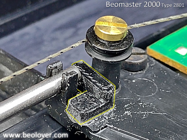
There appeared to be a missing pieces (a plastic tab) that keeps the metal rod for the dial assembly from pulling out of place.


I fashioned a second 3D part to keep metal rod in place. It too was installed using some epoxy.


That was not the end of the problems for the right side dial cord pulley though.

I could easily see that the pulley assembly was loose and would not remain in place when the tension of the dial cord was pressing on it.

It turns out there were some cracks in the plastic mounting post for that pulley assembly.
So the mounting screw would expand the cracked mounting post when pressure from the dial cord is applied.

For that repair I made a ring for the post so the cracks in the post couldn't expand.

That work out really well.  Satisfied that repair would work I epoxied the ring in place.


This Beomaster should be ready for further testing once the replacement lamps and new dial cord arrive.